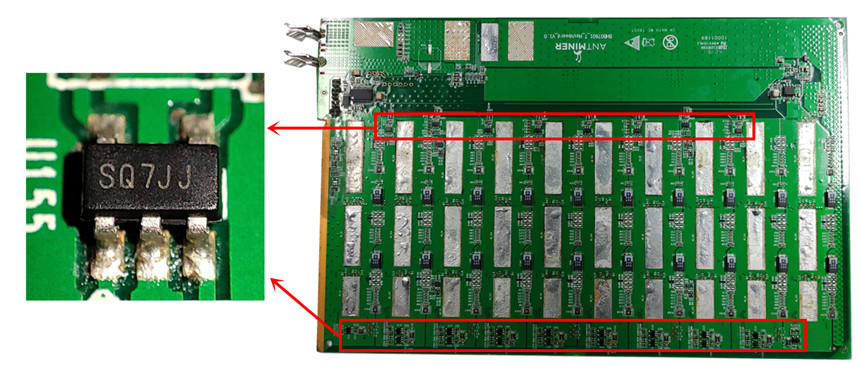


T17 hash board (BHB07601) has a total of 30 BM1397AG chips. It adopts double-sided heat dissipation (there are heat sinks on both sides of the hash board). And during long-term continuous operation, some components will easily fail. The easily damaged electronic components of the hash board are described as follows.
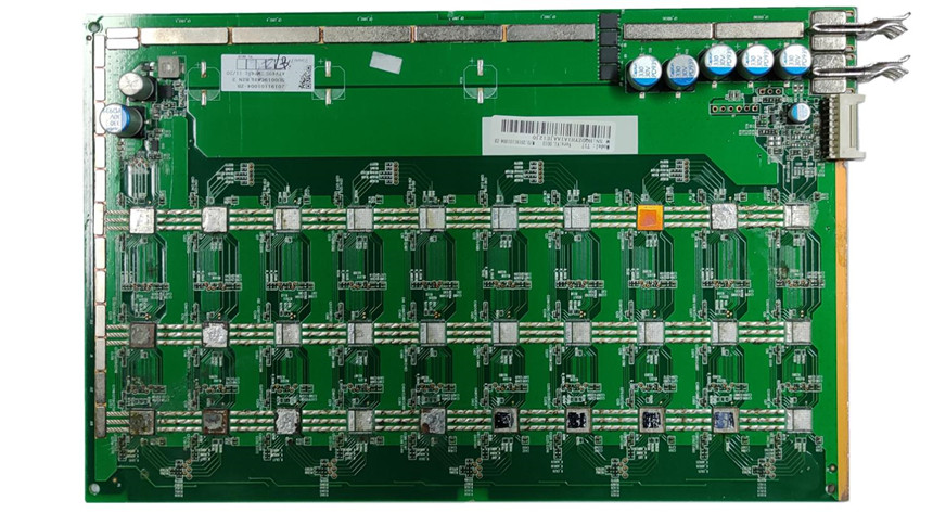
Schematic diagram of T17 hash board: front, the heat sinks have been removed, this type of heat sink is soldered to the chip by solder paste, visible ASIC chip.
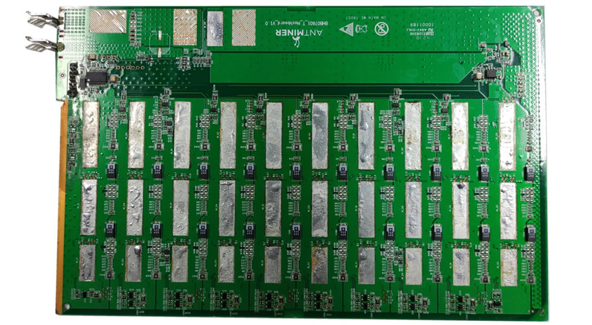
Schematic diagram of T17 hash board: back, the heat sink is fixed on the hash board with soldering paste.
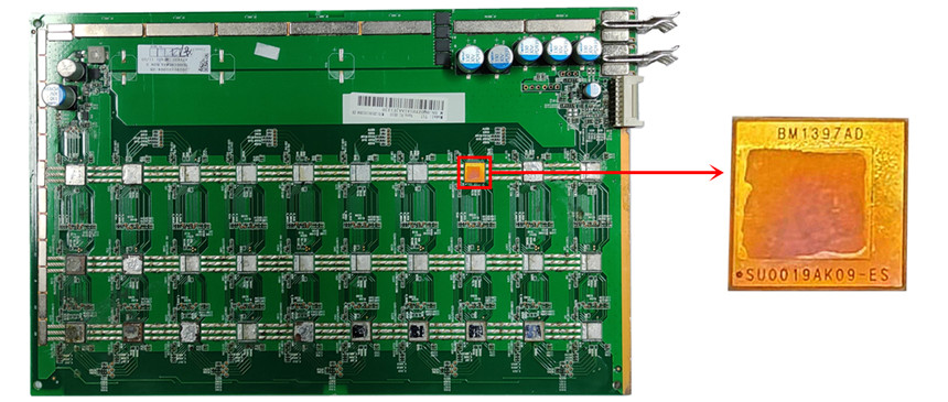
Easily damaged part 1: ASIC chip (BM1397AG)
There are a total of 30 BM1397AG chips on the whole board. They are distributed under the front heat sink and connected to the heat sink through the thermosetting adhesive. In daily maintenance, ASIC chip damage is widespread.
After the ASIC chip is damaged, the miner will have no hashrate or low hashrate. The backstage interface will display the number of chips lower than the actual number. When testing with a test fixture, the specific location (chip number) of the bad chip will be prompted. In some cases, the low hashrate of a single chip will also lead to a low hashrate or no hashrate of the entire hash board. In this case, only the test fixture can be used to locate the faulty chip.
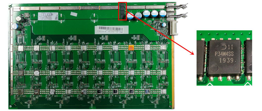
Easily damaged part 2: MOS chip (P34M4SS 1939)
There are 4 MOS chips in the whole board, and the MOS chip is located on the upper right side of the front of the hash board.
MOS is a field effect tube, which exists in the hash board voltage regulator circuit. After the MOS chip is damaged, it will cause no voltage or abnormal voltage on the whole board. Usually when prompting 0 ASIC, check the voltage domain voltage first, if it is abnormal, it is most likely to be a MOS failure. This component can be replaced by other models, please check the chip data sheet.
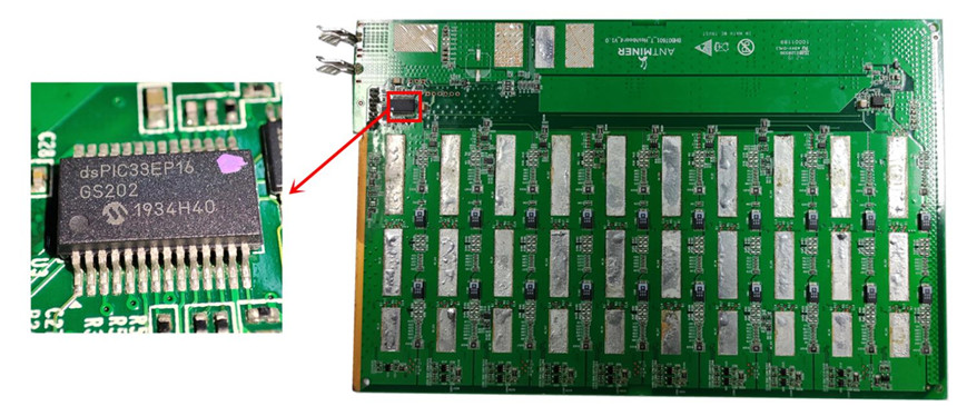
Easily damaged part 3: PIC chip (dsPIC33EP16)
The PIC chip dsPIC33EP16 is located on the upper left side of the reverse side of the hash board, and there is a total of 1 PIC chip on the whole board.
This component is used to store the configuration data of the hash board (ie PIC file). After the chip is damaged, the hash board will not operate, and the voltage and resistance of the whole board will be normal, but it will not start normally.
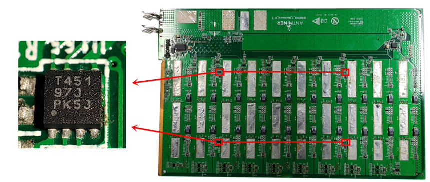
Easily damaged part 4: Temperature sensor chip (T451 71J)
There are 4 T451 temperature sensor chips on the whole board, which are located on the back side of the hash board. Note: The temperature sensor chip exists under the heat sink on the reverse side, and the radiator needs to be disassembled to be discovered.
If the chip is damaged, it will cause abnormal temperature reading, and the hash board will not start when the temperature is too low (the background log indicates that the temperature sensor reading fails) or the temperature will stop running when the temperature is too high.
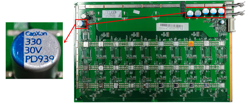
Easily damaged part 5: solid capacitor (330 30V)
There are 6 solid capacitors 330 30V on the whole board, 5 on the right side of the front of the hash board, and 1 on the left side.
The main function of this component is to filter, rectify and store energy. The 5 capacitors at the power input interface of the T17 hach board (on the right) are mainly used for filtering and rectification. If the one of the 5 capacitors is damaged will cause abnormal voltage on the hash board and damage other components. A capacitor near the inductor (on the left) is mainly used for rectification and energy storage. After damage, it will affect the operation of the boost circuit and cause the hash board to not operate.
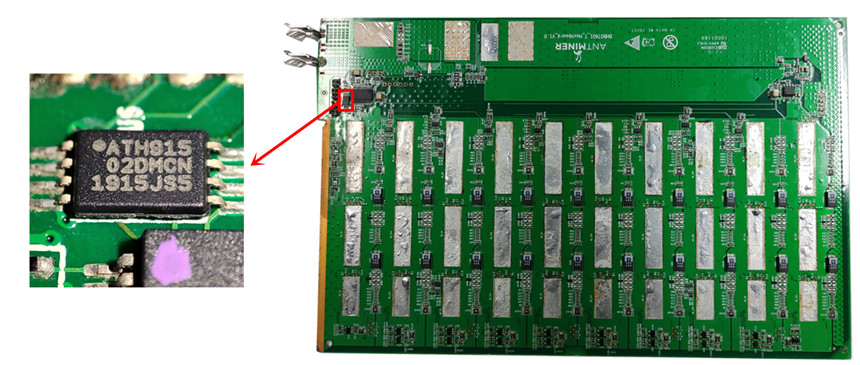
Easily damaged part 6: EEPROM memory (02DMCN)
This component is mainly used to store EEPROM data and is located on the upper left side of the back of the hash board. If the chip is damaged, the entire miner will not run (not a single board will not run), because there are three hash boards in the Antmienr T17 and the hash boards must maintain the same EEPROM data to be recognized by the control board. If one of them is damaged, the miner will report an EEPROM error in the background and stop starting.
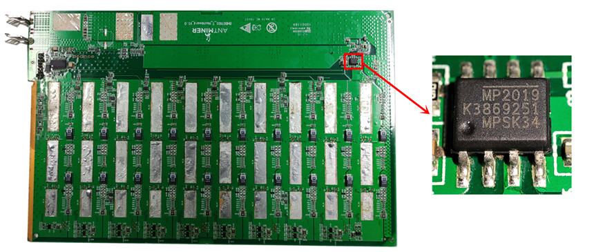
Easily damaged part 7: Low dropout voltage regulator chip (MP2019)
The low dropout voltage regulator chip (MP2019) is located on the upper left side of the reverse side of the hash board. The main function of this component is over-voltage protection, over-current protection, and over-temperature protection, the internal MOSFET is integrated. After damage, it will cause abnormal voltage in the voltage domain, or no voltage, under-voltage and other faults, which will cause the miner to not operate.
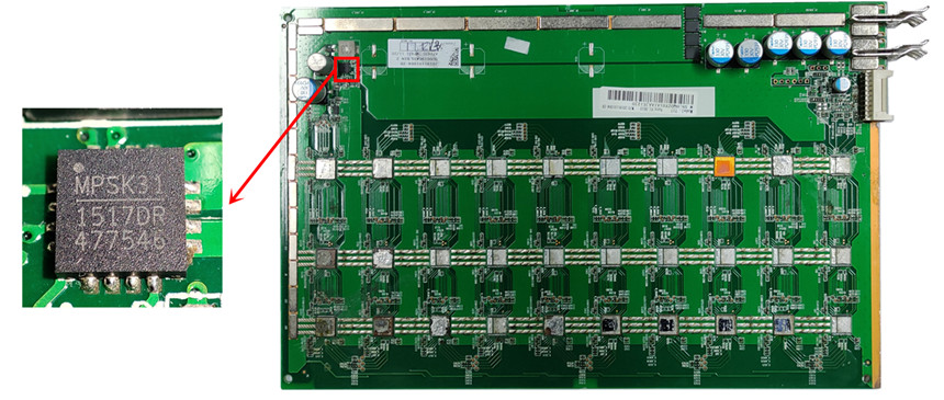
Easily damaged part 8: Boost converter chip (MP1517DR)
The boost converter chip (MP1517DR) is located on the upper left side of the front of the hash board. The main function of this component is to detect and control the output voltage of the boost circuit of the hash board, and adjust it to a suitable voltage in time, the internal integrated FET voltage regulator module, after damaged will cause no voltage in the back section of the MOS circuit. when the chip fails, the MOS test the output is normal, but there is no voltage in the voltage domain.
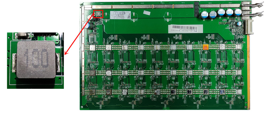
Easily damaged part 9: Inductor 100.
The Inductor 100 is located on the upper left side of the front of the hash board. The main function of the inductor is to stabilize the current of the hash board and suppress the electromagnetic interference of the circuit board. After damage, the hash board is easily affected by the electromagnetic interference of the adjacent hash board, which affects the 25Mhz clock signal, resulting in unstable operation of the hash board, for example: Low force, inaccurate temperature monitoring, repeated start and other faults.
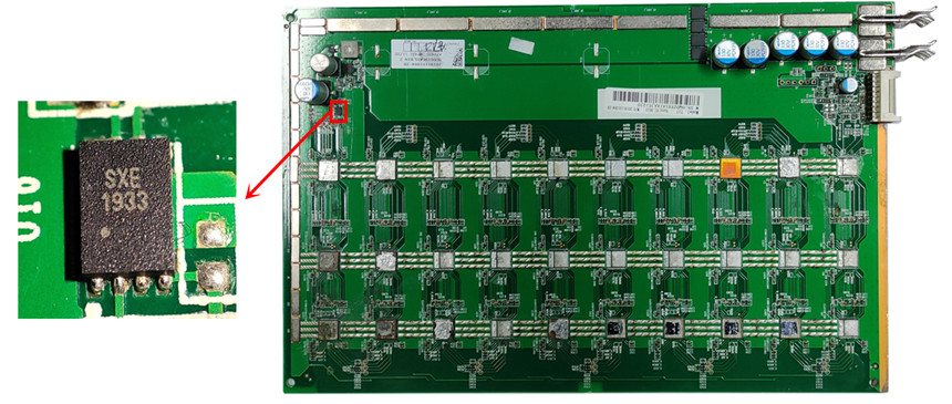
Easily damaged part 10: Voltage monitoring chip (SXE1933)
The voltage monitoring chip (SXE1933) is located on the upper left side of the front of the hash board. The main function of the voltage monitoring chip is to monitor the real-time voltage in the voltage domain of the hash board. This component is located at the back of the boost circuit. After damage, the front boost chip will not receive the returned data and stop working, causing the hash board not to start. The hash board is easily affected by the electromagnetic interference of the adjacent hash board, which affects the 25Mhz clock signal, resulting in unstable operation of the hash board, for example, low force, inaccurate temperature monitoring, repeated start and other faults.
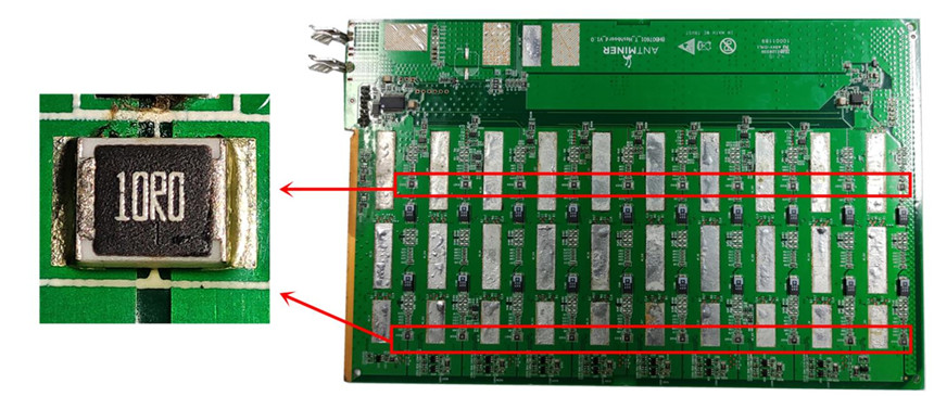
Easily damaged part 11: SMD resistor (10R0)
There are 20 chip resistors on the whole board, distributed between the voltage domains on the back of the hash board. The main function is to conduct the voltage domain of the whole board in a limited manner to realize the voltage balance between the voltage domains. After damage, it will cause voltage in the voltage domain to be poor, resulting in unstable operation of the Hash board.
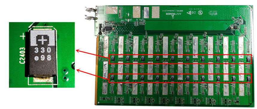
Easily damaged part 12: chip capacitors (330e98)
There are 20 chip capacitors on the whole board, distributed between the voltage domains on the back of the hash board. The main function is to filter and rectify, to achieve voltage balance between the voltage domains. After damage, it will cause a voltage difference in the voltage domain, resulting in a hash board's unstable operation.
Easily damaged part 13: Voltage domain steady current chip (SQ7JJ)
There are 26 voltage domain steady current chips on the whole board, distributed under the heat sink on the reverse side of the hash board. The function of this component is to stabilize the voltage and provide a preset starting current to the voltage domain where it is located. After the chip is damaged, it will cause the voltage domain to fail. Because the voltage domain is in series, it will cause no voltage in the back-end voltage domain, and the voltage domain involved will stop operating.
