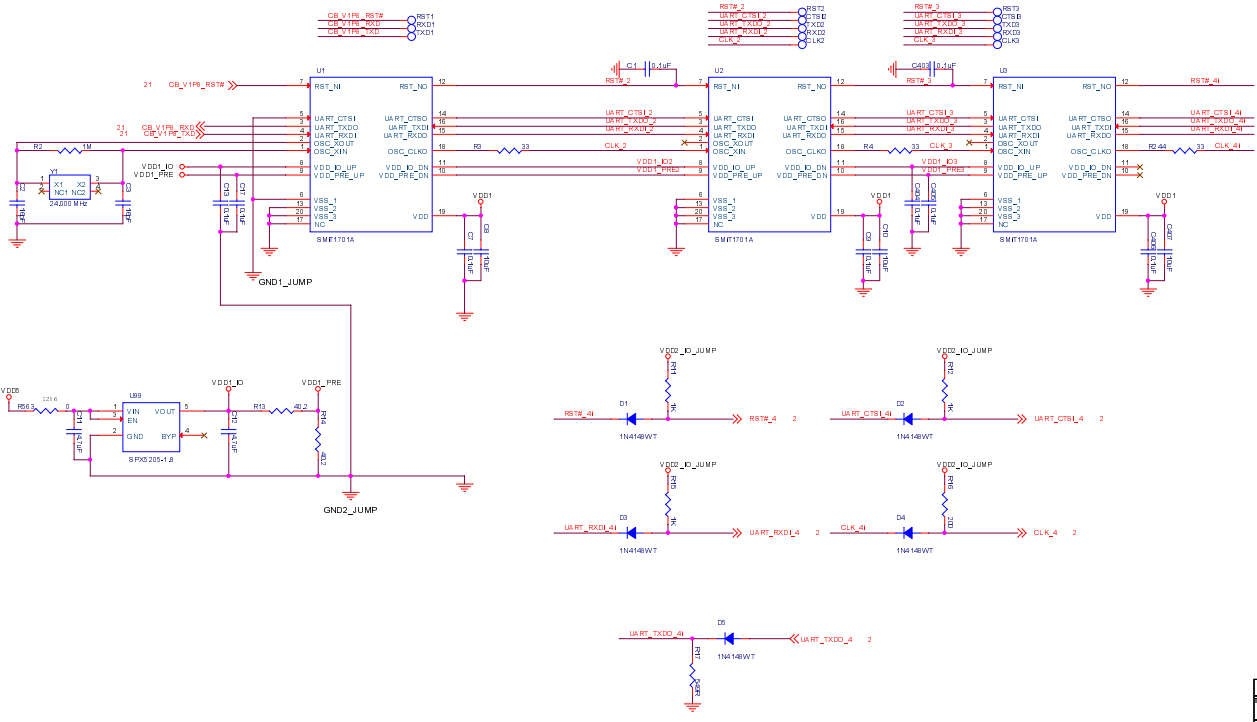
M3 is composed of 21 voltage domains in series, each voltage domain has three 1701A (1701B) chips in parallel, and the whole board is composed of 63 chips. Each voltage domain has an independent LDO that provides 1.8V and 0.9V voltages and is composed of RST.CTS.RXD.TXD.CLK. M3 has only one 24M clock and temperature sensor. The upper and lower sides of the whole board are equipped with heat sinks to form a complete hash board.
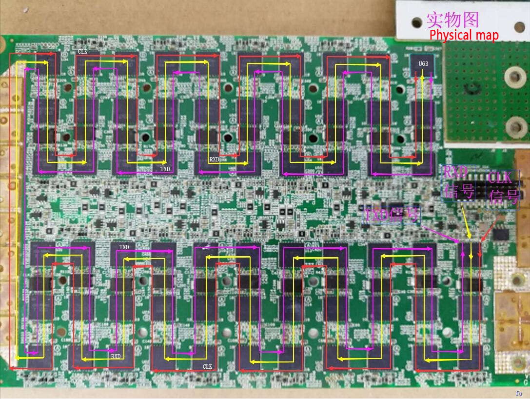
1. Signal direction:
Schematic diagram
Physical map
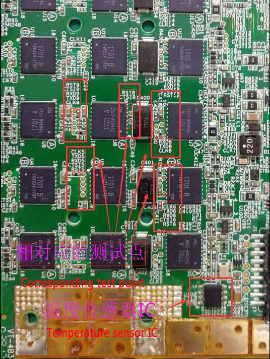
2. Inter-domain composition and value, test points: CLK is 0.9~1.0v, RXD is 1.8V, TXD is 1.8V, RST test is 1.8V, after the test is 0V, inter-domain voltage is 0.5~0.7V, domain The resistance value is between 5~7 Ω.

3. There are test points and temperature sensors between the chips.
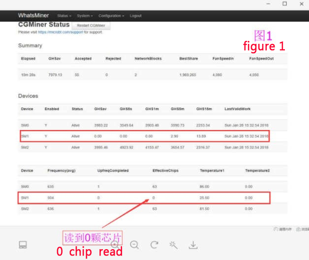
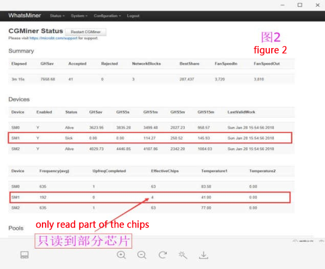
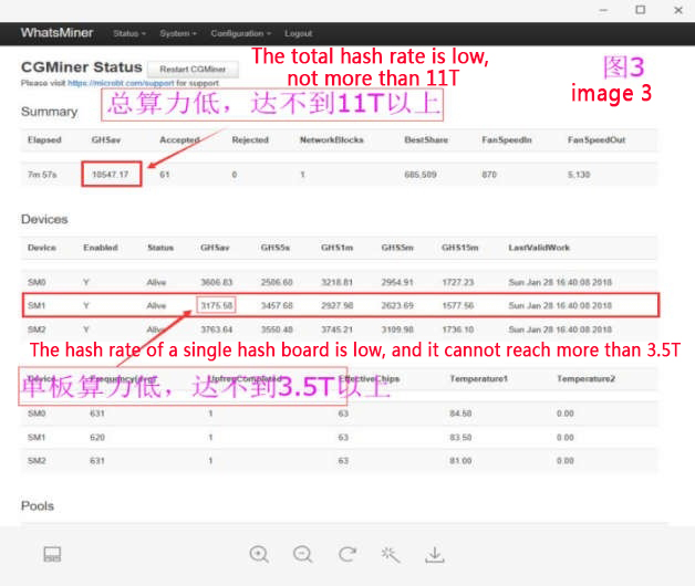
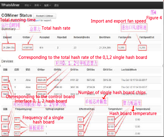
The system shows that the hash board is faulty during maintenance: It contains the following three phenomena: unable to read the chip (Figure 1), read only part of the chip (Figure 2), and low hash rate (Figure 3), eligibility criteria shown in Figure 4.
1. Introduction to the system interface display
Find the faulty miner, and then find the corresponding hash board to be repaired.
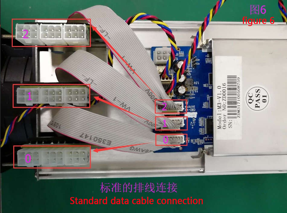
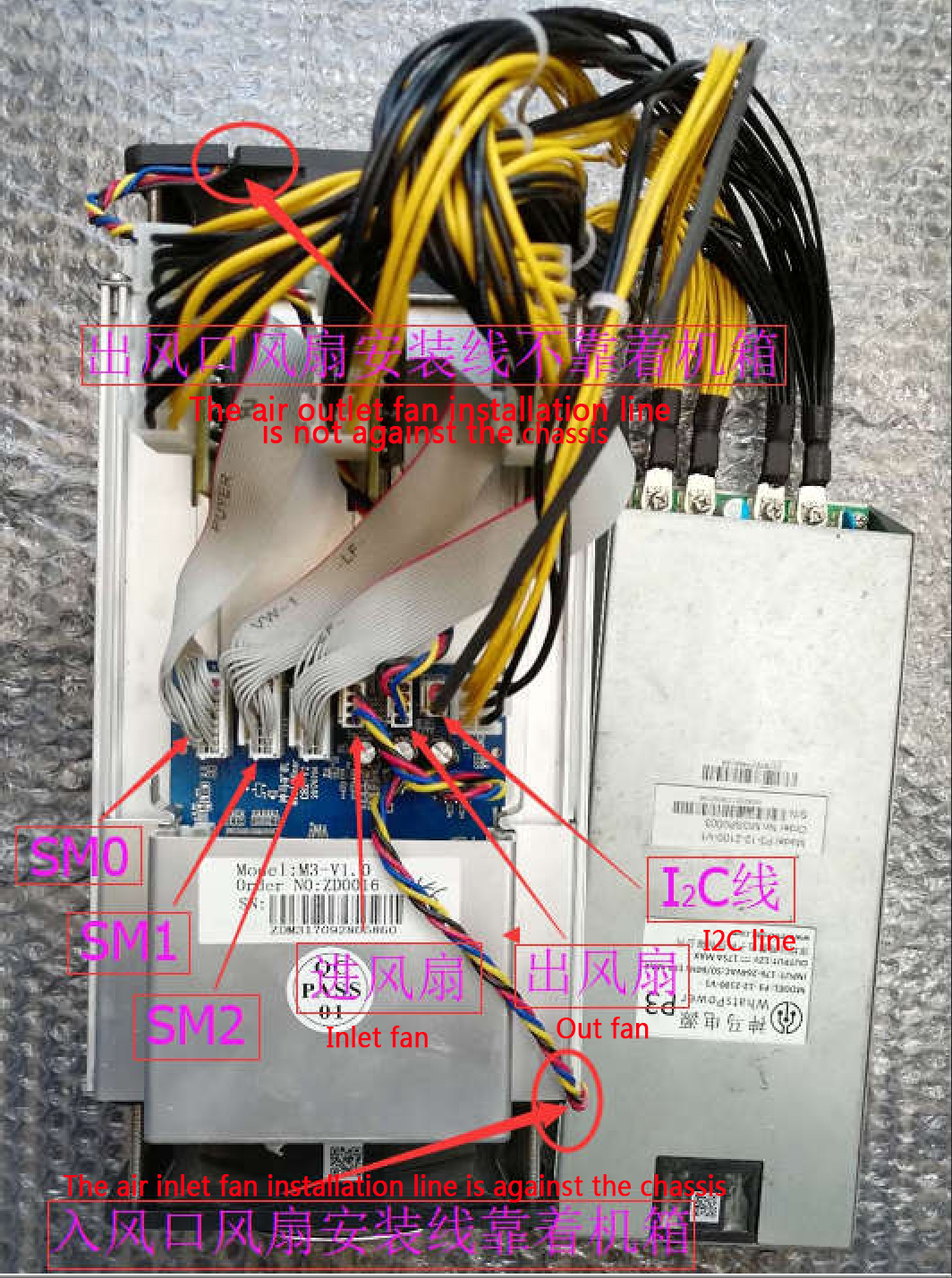
1. The standard connection is the control board SM0, SM1, SM2 interface is the corresponding system and hash board SM0, SM1, SM2 (Figure 6)
2. The non-standard connection is the interface shown by the system and the control board SM0, SM1, SM2, not the SM0, SM1, SM2 interface of the corresponding hash board (Figure 7)
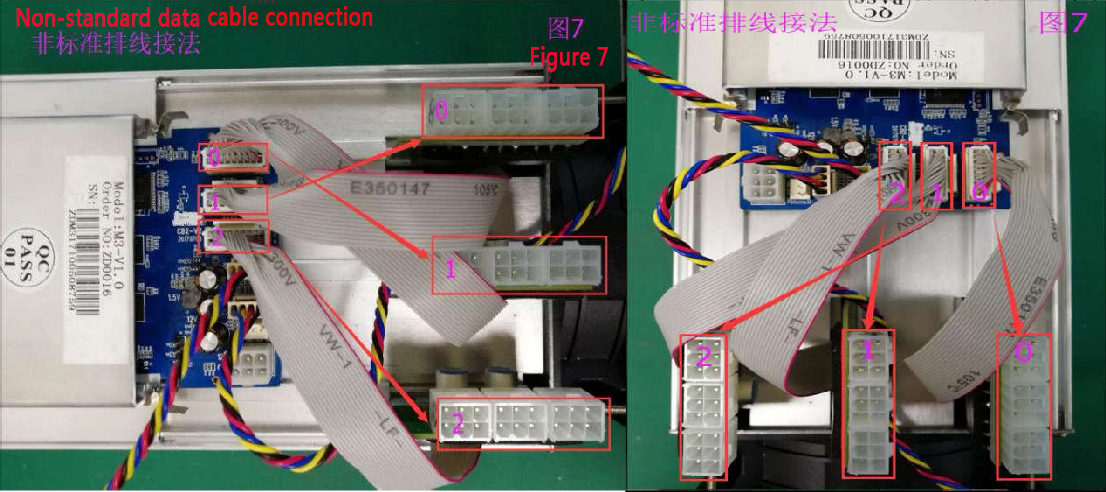
3. For the sake of safety, it is especially reminded that in order not to disassemble the faulty hash board by mistake, take the hash board corresponding to the data line of the control board interface SM0, SM1, SM2 as the standard, and remove the hash board to be repaired. The SM0, SM1, and SM2 on the control panel correspond to the system displays SM0, SM1, and SM2, which will not change!
Hash board repair1. Can't read the chip
The monitoring system is shown in Figure 1 above
Use the test software (test-readchipid) to test read-only chips to 0. The interface is shown as follows:
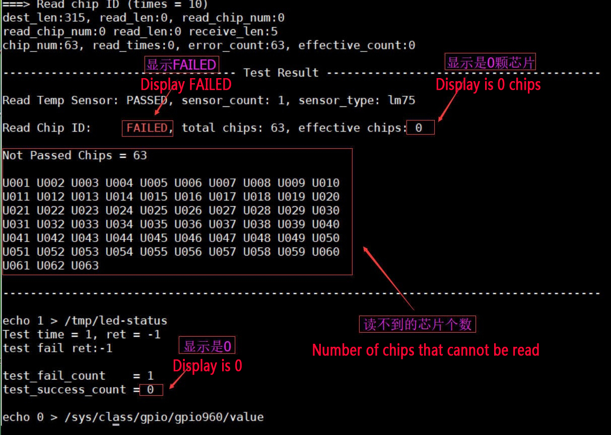
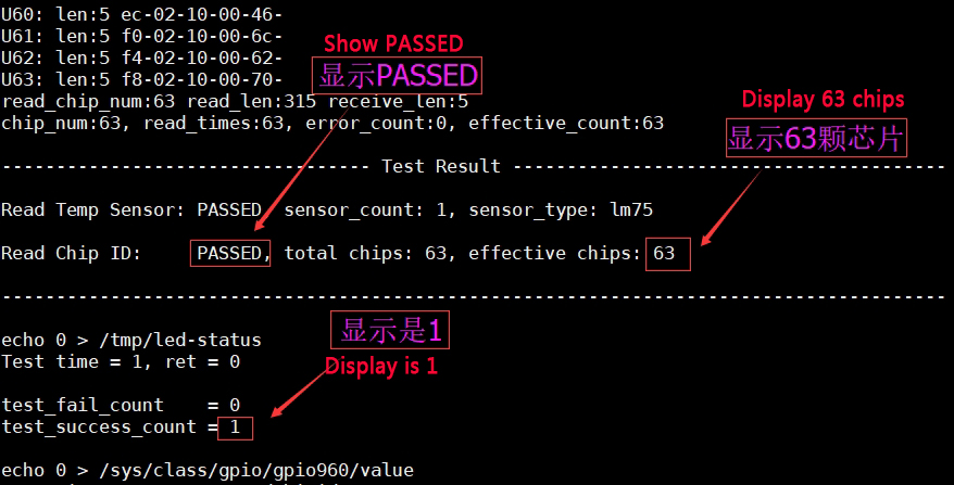
Read the display interface of all 63 chips.
Repair example: software test shows 0 chips, use the multimeter Fluke 15b+ DC voltage to measure the CLK test point (as shown in Figure 1b), and the measured value is 0.3V, and the 24M clock voltage is measured as 1.8V (as shown in Figure 2d), so the u1 chip is judged wrong, replace u1, and the power-on test is OK.
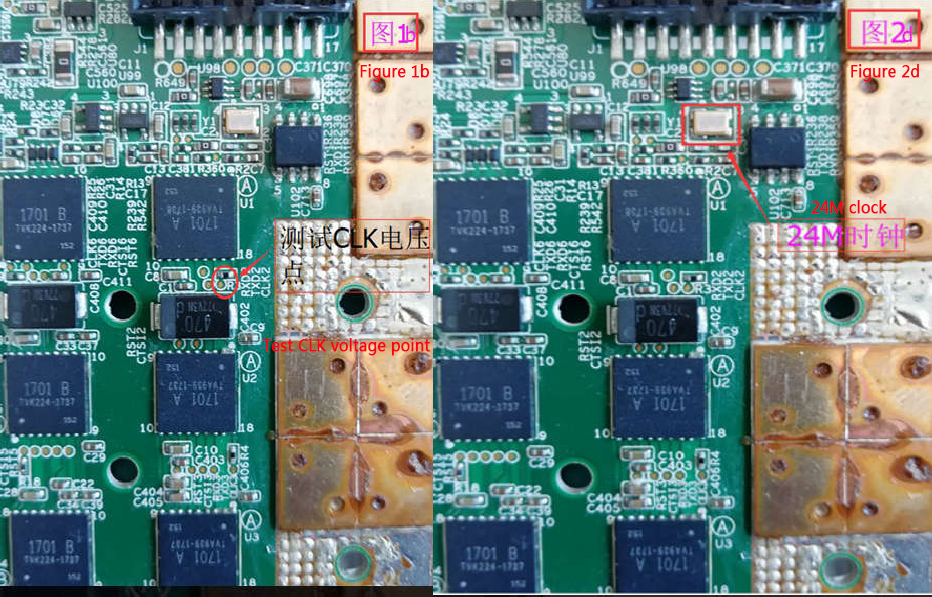
Summary: M3 clock is provided by u1 to u2, u2 is provided to u3 and transmitted to u63. The chip cannot work without the clock, so 0 chips are read.
2. Read only to part of the chip The test software can only test 49 chips, and the interface display is as follows:
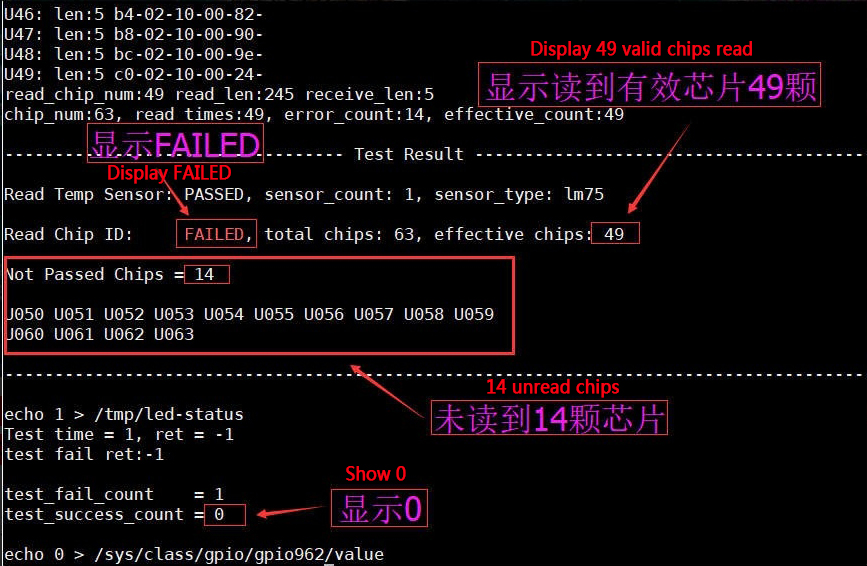
The software test reads 49 chips, uses the multimeter's DC voltage file to measure u49 CLK, RXD, TXD voltage is normal, inter-domain voltage and 1.8V are normal, 0.9V voltage is 0, replace u49 voltage is normal, test OK.
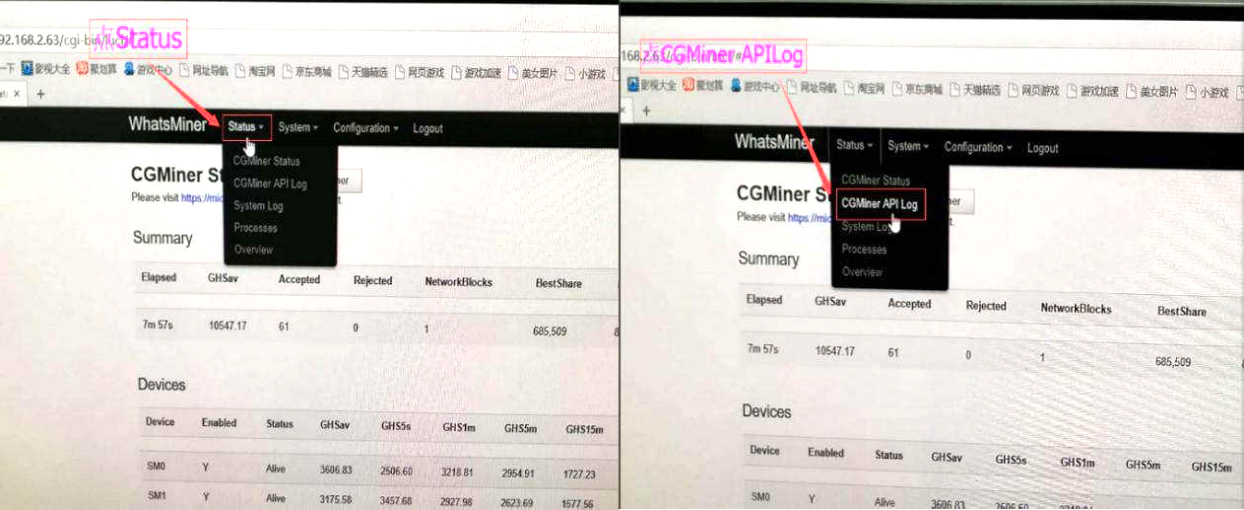
3. The hash rate of a single hash board is low The monitoring system displays as shown in Figure 3 above Maintenance example 1: To enter the system interface, first click Status and then CGMiner APILog to enter the backstage.
Go to the backstage to find SM1 and find the chip location with a low core count, as shown below:
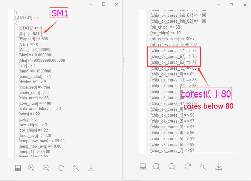
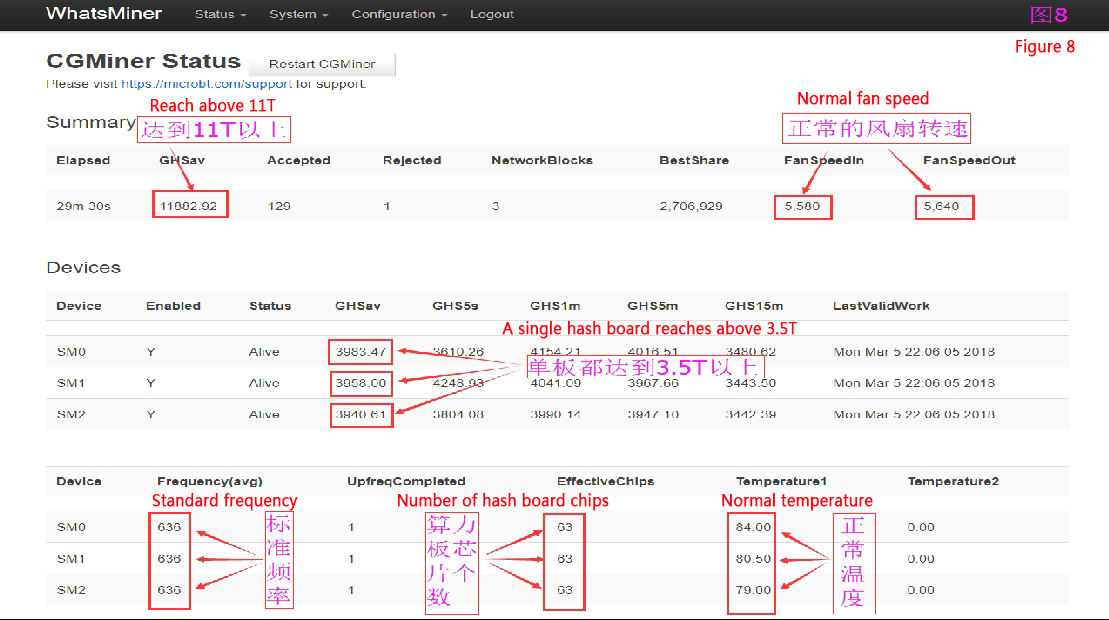
U17/72, u57/73, u52/77 are all lower than 80 cores; replace u17, u57 and u52, power on and test OK, as shown in Figure 8.
Repair example 2: Test with the test software (test-hashboard), the interface is displayed as follows (Special reminder: Use the test-hashboard to test, you must install the upper and lower heat sink to test. Otherwise the chip will be severely burned!)
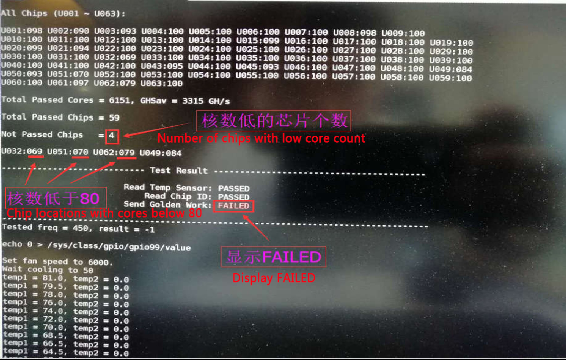
U32/69, u51/70, u62/79 are all lower than 80 cores; replace u32, u51, u62, and then use the test software to test, as shown in Figure 9:
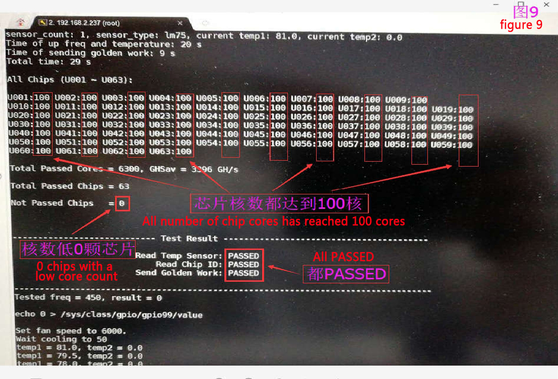
Test OK, install aging test. Note: The test software has only 2 test commands: test-readchipid and test-hashboard.
We rarely use oscilloscope tools in our repairs. Here is a brief introduction:
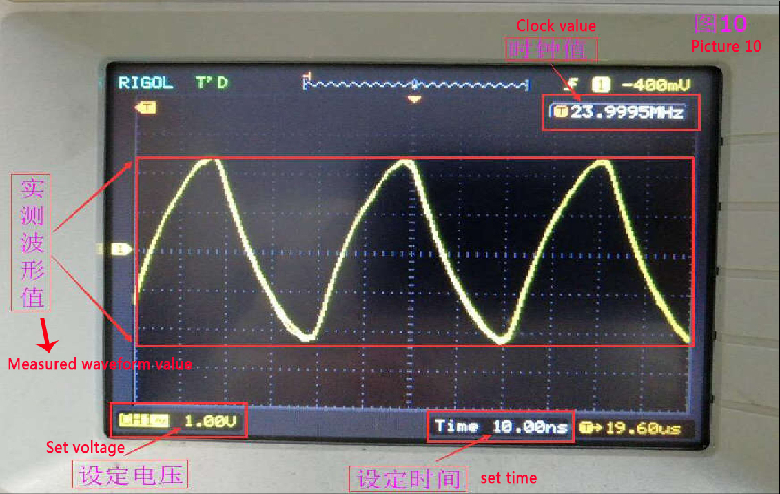
1. Measure the CLK signal, set the oscilloscope to 1.0V, set the time to 10.0ns, and the measured clock is 24M, as shown in Figure 10.
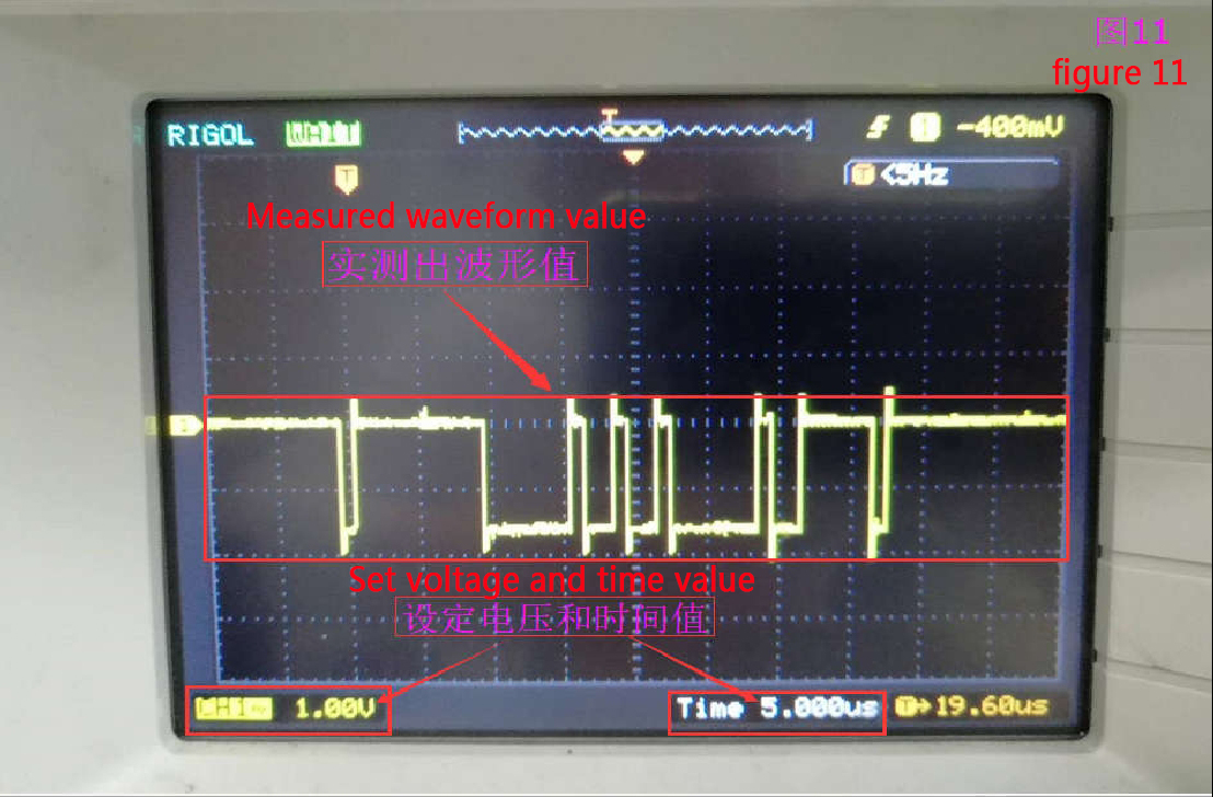
2. Measure the RXD signal, set the oscilloscope to 1.0V, set the time to 5.0us, and measure a waveform around 1.8V, as shown in Figure 11:
3. Measure the TXD signal, set the oscilloscope to 1.0V, set the time tox 5.0us, and measure a waveform with a voltage around 1.8V, as shown in Figure 12:
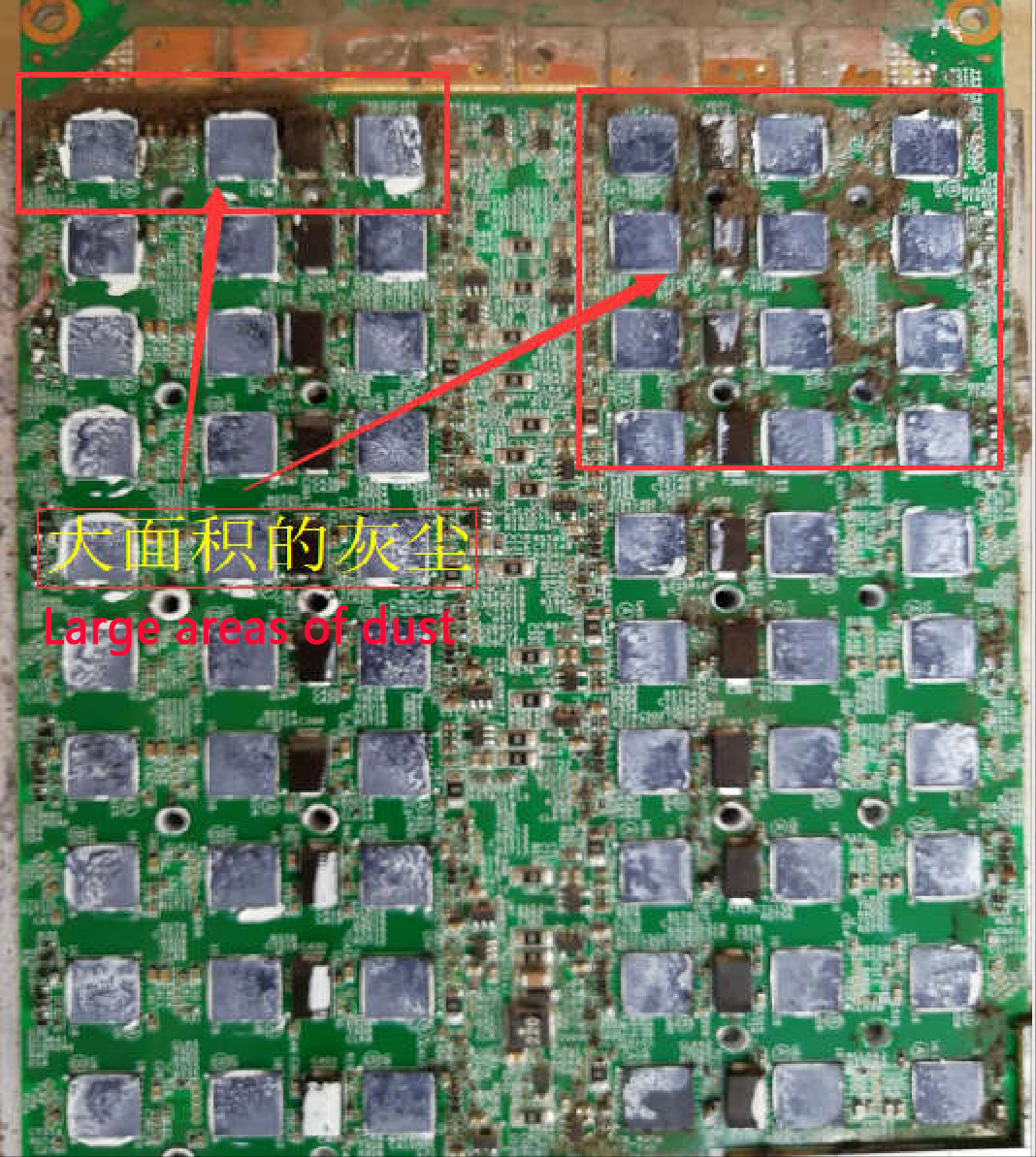
The oscilloscope model is different. The setting value is also different. The above is just for reference. Pay attention to some details in daily maintenance to avoid unnecessary losses. For example, when plugging in or unplugging the data cable and 12V6P cable, be sure to cut off the power. Also, regularly check whether the fan speed slows down or runs at a low speed. Clean the dust regularly, more than twice a month. If the dust accumulates on the hash board and becomes damp, it will easily cause a short circuit. The picture of the failure of the hash board caused by the failure to remove the dust in time:
Picture of the whole miner installed:
Dear Customers,
Hello, May 1-5, 2026 (GMT+8) is China's May Day, and international logistics will be suspended. Our company will suspend shipments on the afternoon of April 30, 2026, and resume warehouse shipments on May 6 (GMT+8). We are deeply sorry for the inconvenience caused to you. Thank you for your trust and support.
Best wishes,
ZEUS MINING CO., LTD.