

The Avalon 3300W power supply suitable for Avalon A1066 / A1066Pro / A1166 / A1166Pro / A1246 miners is owned by the majority of miner owners. In order to allow more mine operation and maintenance personnel to quickly and accurately repair Avalon 3300W 3600W PSUs and reduce losses caused by downtime, We organize and share Avalon 3300W 3600W PSU repair manuals for reference only.
Ⅰ. Understand the PSU parameters
1. PSU 3300W: PSU3300-03
Input voltage: 200-285VAC 50/60Hz 16A Max
Output voltage: 11.5V-14.5V ⎓ 3100W
12V ⎓ 200W
2. PSU 3600W: PSU3300-03 PLUS
Input voltage: 185-285VAC 50/60Hz 16A Max
Output voltage: 11.5V-14.5V ⎓ 3400W
12V ⎓ 200W
Ⅱ. Working principle of Avalon 3300W 3600W power supply
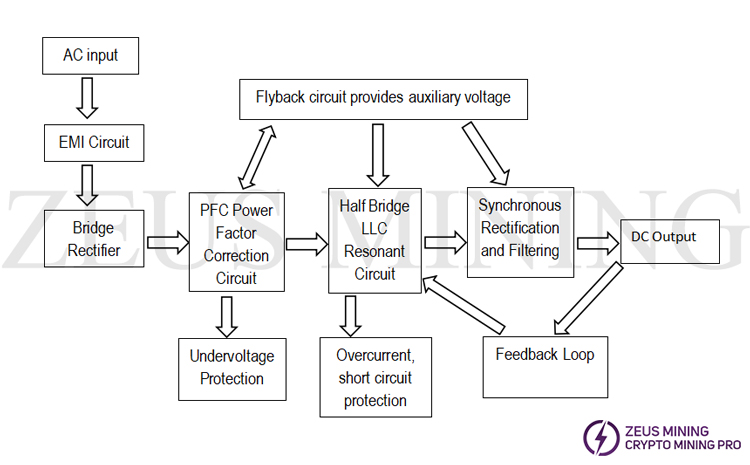
The power supply contains multiple main circuits, such as: EMI circuit, bridge rectification, power correction circuit, main board bridge LLC resonant circuit, auxiliary half bridge LLC resonant circuit, flyback circuit, MCU control circuit, protection circuit, main synchronous rectification filter circuit , auxiliary synchronous rectification filter circuit, etc.
The specific working principle of the power supply:
1. After the PSU is powered on, the input AC voltage is converted into DC voltage through the EMI circuit and bridge rectifier circuit;
2. The DC voltage generates 18VCC after passing through the flyback circuit; then the 18VCC here supplies power to the relay, auxiliary circuit LLC2 IC, main circuit LLC1 IC and PFC chip.
3. After the PFC chip works, its voltage will be boosted, and the ICs of the main circuit LLC1 and the auxiliary circuit LLC2 start to work.
4. After the LLC1 chip works, it will generate the main output voltage through the LLC resonant circuit, and then perform synchronous rectification.
5. After the LLC2 chip is working, it will also generate an auxiliary output voltage through the LLC resonant circuit, and work synchronously.
6. After the auxiliary voltage is converted, it supplies power to the MCU chip, and provides software communication, control and protection functions.

Ⅲ. Maintenance ideas for common faults
1. Hardware failure
Specific methods for analyzing fault types:
① First remove the power supply that is not working properly from the miner;
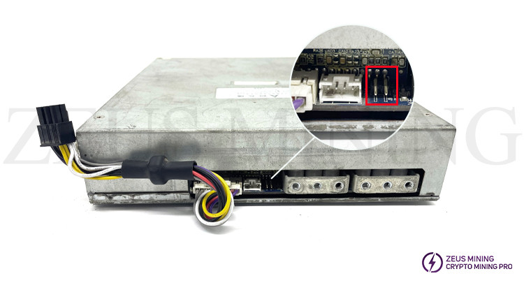
② As shown in the figure below, short-circuit the 2 pins on the right side of the positive terminal of the power supply;

③ Directly energize the PSU unit. It should be noted that the miner cannot be connected at this time;
④ Measure the psu input voltage. Adjust the multimeter to the DC voltage gear, connect the red test lead to the positive pole, and the black test lead to the negative pole. If the voltage is greater than or equal to 11.9V, it can be preliminarily judged that the power supply is normal, and the miner needs to be subjected to an aging test; but if the voltage is less than 11.9V, it may be that the PSU has failed.
2. Troubleshooting ideas and methods for no output failure of the power supply
(1) First confirm whether the sockets of the power input and output ports are loose, and whether the DC wire is damaged. If there is a problem, the DC wire needs to be replaced to ensure a reliable connection.
(2) The 2nd step is to confirm that there is no poor welding or short circuit on the power board, check whether there is tin slag or tin beads on the back of the power board, whether there is any problem with the welding of components, and visually inspect whether the components are corroded or oxidized. If there has something wrong, replace components.
(3) If there is no problem, turn on the PSU and check. After energizing, fluctuate the IO switch to confirm whether the relay has a sound? If there is no sound, you need to check whether K01, K02, RT01, RT02, BD01, BD02 are damaged, and if damaged, replace the components.
(4) Check whether the PFC voltage is around 380V-405V. If not, check whether U01, Q01, Q05, BD01, BD02, D01 and D08 are damaged, and replace the components if damaged.
(5) Check whether the powering voltage of UL1 is about 15V, if not, check the VCC powering circuit (Q24) provided by the flyback board.
(6) Check whether UL1, Q30, Q40, Q25, Q39, Q15, Q16, Q17 and Q18 are damaged, and replace the damaged components.
(7) Check whether the output is short-circuited. If there is a short circuit, you need to check the MOS tubes Q26-Q29, Q31-Q38, Q41-Q44, and Q56-Q59 in sequence; then check whether U17 and U18 are damaged, and if they are damaged, replace the damaged components.
(8) If the output is not short-circuited, check whether the MUC board is faulty, and replace the damaged device. After repairs are complete, start retesting.
3. Reasons for no power output and specific maintenance methods
Reason 1: F01 Open-circuit
Specific repair method:
The overvoltage or overcurrent of the power supply is abnormal, causing the AC fuse F01 to blow.
Adjust the multimeter to the diode gear, and measure the L cable and N cable of the AC socket. If no value is displayed, F01 is open-circuit. If there is a value, it means the AC cable is normal.
Reason 2: The high-voltage BUCK board is damaged due to the harsh working environment.
Specific repair method:
Repair method: Check whether the UF1, QF1, QF2, RF9, RF10, RF17, RF18, RF19, RF14 chips are damaged. If damaged, replace component.
Reason 3: The AC bridge rectifier diodes BD01 and BD02 are damaged by too much dust.
Specific repair method:
Replace BD01, BD02, F01, pay attention to replace the equipment shell. The four pins of the bridge rectifier diode should cover the bushing, and the heat sink should be coated with thermal paste.
Reason 4: The pin of the small bridge rectifier diode BD03 is corroded and damaged.
Specific repair method: replace BD03.
Reason 5: The cooling fan is damaged.
Specific repair method:
(1) PFC partial blast miner: check U01, Q01, Q05, BD01, BD02, D01, D08, Q02, Q07, Q03, Q08, F01, D02, D09, whether the peripheral chip resistors are damaged, if damaged, replace the device.
Apply cooling cream when replacing BD01, BD02, Q01, Q05, D01, and D08, and cover with heat shrinkable tube when replacing F01.
When measuring whether the U01 chip is damaged, turn the multimeter to the diode gear and check whether there is a voltage difference of about 0.5V between VCC and ground. If not, replace U6: NCP1654.
(2) The main LLC part of the miner: check whether Q30, Q40, Q25, Q39, Q15, Q16, Q17, Q18, UL1, R1, R2, R16, R18, D9, D12 are damaged, if damaged, replace the device. Be careful to apply thermal paste when replacing Q1 and Q8. When measuring whether the U2 chip is damaged, turn the multimeter to the diode gear and check whether there is a voltage difference of about 0.5V between the two ends of C94. If not, replace U2: NCP1399AM / 1399AC.
Reason 6: Corrosion of components or circuits leads to short circuit of synchronous rectification low-voltage MOS.
Specific repair method:
Check Q26, Q27, Q28, Q29, Q31, Q32, Q33, Q34, Q35, Q36, Q37, Q38, Q41, Q42, Q43, Q44, Q56, Q57, Q58, Q59, U17, U18, Q45, Q46, Q47 , Q48, Q49, Q50, Q52, Q7 5 and resistor 2R2 are damaged, if damaged, replace the device. The synchronous rectification MOS5 is a group, generally only one is broken, and needs careful inspection.
Reason 7: The strong voltage breaks down the auxiliary LLC2 small board.
Specific repair method:
Check whether Q16 and Q11 are short-circuited. If the above situation occurs, replace the components. Check whether there is a voltage difference of about 0.5V between the VCC of the UL2 chip and the pin 5. If not, replace with UL2: 1399AM / 1399AC.
Note: After replacement, repaint the conformal paint.
Attention:
① Damage to the fan will cause the temperature of the PSU to rise, resulting in an explosion. The device damage can be divided into two parts, the PFC part explodes and the LLC part explodes. The measurement of each part is analyzed.
②The material to be replaced must correspond to the model, and don’t think it’s the same material just by looking at the appearance.
4. Software failure
After the repair is complete, power up the PSU again and measure the voltage. After the voltage is normal, we need to connect a miner with qualified performance (indicators such as hash rate and power consumption ratio are qualified) for aging test. If there is still no hash rate, low hash rate, abnormal PS data or other related error codes, it is initially judged that the power supply software circuit is faulty; if hash rate and power consumption ratio are normal after connecting the miner to aging test, it means that the power supply is OK .
If it is still abnormal, the maintenance method: remove the MCU small board STM8S005C6T6 IC chip and the resistor container parts in sequence, and replace them accordingly.
Ⅳ. Maintenance Precautions
(1) When confirming that the power supply is bad, be sure to use the protection switch to avoid explosion and injury.
(2) Pay attention to electrostatic protection during maintenance, and wear an anti-static wristband.
(3) The temperature management of the electric soldering iron is recommended to be controlled at 380°C~420°C.
(4) When replacing materials, products of the same model and specification should be used. Alternative materials may not be used without permission.
(5) Carry out defective product identification for repaired and replaced defective products, optimize on-site positioning management, and avoid mixing qualified products.
(6) Record the power supply S/N serial number, failure phenomenon, failure cause, maintenance method and other information, and provide maintenance record sheets regularly.