

PicoBT is a professional miner tester that electronics repairmen and engineers can diagnose and repair more than 120 models of Hashboards and 20 models of smart power supplies manufactured by Innosilicon, Whatsminer, Antminer, Aixin, Cheetah and Dragon companies.
Compared to traditional miner repair methods, PicoBT tester with unique its features can reduce the diagnostic time by at least 10 times, and increase the accuracy of diagnose by 4 times in troubleshooting minor components, namely Hashboards and smart power supplies units.
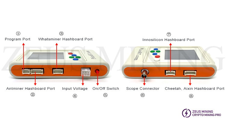
① Programming Port: Used for updating PICOBT test files.
② Antminer Hash Board Interface: Used to connect the Antminer hash board under test; used to copy, flash, and save EEPROM files for Whatsminers and Antminers. Please use an 18-pin data cable to connect to this interface on the tester. Supported Antminer hash board models are as follows:
L9, S21+, S21+ Hydro, S21 Hydro, S21PRO, S21XP, S21 Imm, S21, T21, KS5PRO, KS5, KS3, S19K Pro, S19pro, S19j, S19J pro, S19A, S19A pro, S19_88, T19Hydro, S19Hydro, S19pro Hydro, S19J PRO No Pic, S19XP, S19XP Hydro, S19AL, S19+, S19i, S19PRO+ Hydro, S19PRO+, S19J PRO+, T19, S19, KA3, L7, D7, K7, T17, T17+, T17e, T17pro, S17, S17+, S17e, S17pro, S15, T15, S11, S9, S9i, S9j, S9k, S9se, T9+, L3+, S7, etc.;
③ Whatsminer Hash Board Interface: Used to connect the Whatsminer hash board under test; used to copy, flash, and save the EEPROM files of Whatsminers. Please use a 14-pin data cable to connect to this tester interface. The supported Whatsminer hash board models are as follows:
M66, M66s, M66s++, M66++, M63s++, M63S+, M63S, M63, M61, M60, M60S, M56, M56s, M56s++, M53S++, M53++, M53, M50, M50s, M50++, M50s++, M36, M36s, M36s++, M36++, M33, M33s, M33s++, M33++, M32, M32s, M31s, M31s+, M30s, M30s+, M30s++, M21, M21s, M20, M20s, M3V1, M3V2, etc.;
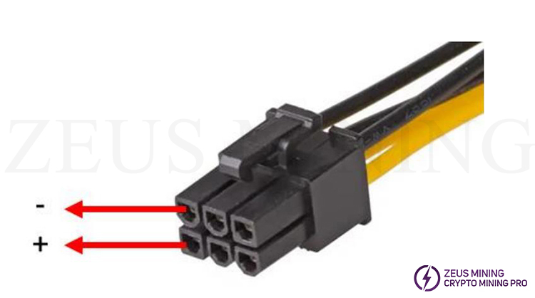
④ Input Voltage: To power on the tester, please connect a standard "ATX 6-pin male" cable to this interface. This interface supports 12V voltage. When inserting the cable, please ensure the polarity (+ and -) is correct.
⑤ On/Off Switch: This switch is used to turn the tester on and off.
⑥ Oscilloscope Interface: This port is used to connect the "oscilloscope probe" to short-circuit the RO/RI/TX signals of Antminers and the TXD signal of Whatsminer to detect the chip health status of the connected hash board.
⑦ Innosilicon Hash Board Interface: Used to connect the Innosilicon hash board under test; please use a 14-pin data cable to connect to this interface on the tester. Supported Innosilicon hash board models are as follows:
T1, T2, T3, T3+, S3, S3+, T3H, A4, A4+, A6, A6+, T2T, T2T+, T2Ti, T2Ts, T2Tz, T2Tzs, T2Tzu, T2Tza, T2Th, T2Ths, T2Thm, T2Thf, T2Th+, T2Ths+, T2Thm+, T2Thf+, T2Thl+, L1, L2, L2HU, L2HF, L2HL, L2HS, T1H;
⑧ Cheetah, Aixin Hash Board Interface: Used to connect the Cheetah and Aixin hash boards under test; please use an 18-pin data cable to connect to this interface on the tester. Supported hash board models are as follows:
A1, Q3, F1, S5, T1.
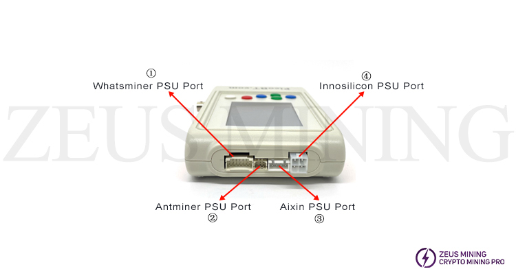
① Whatsminer PSU Port: Supported Whatsminer PSU test models include: P20, P21, P21E, P21D, P221, P221C, P222C, P221B, P222B;
② Antminer PSU Port: Supported Antminer power supply test models include: APW8, APW9, APW9+, APW12;
③ Cheetah, Aixin PSU Port: Supported PSU test models include: TT240015P (A1), HQ2500-A02 (Q3);
④ Innosilicon PSU Port: Supported Innosilicon PSU test models include: G1138(T2), G1240(T2Tz), G1266(T2Th), G1286(T2Th+), G1306(T3+), QB2412-B(T2Tz), QB2412-C(T2Th).
This adapter board is used to connect and test the Whatsminer water cooling miner hash board:
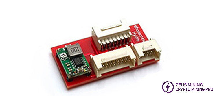
This is the main interface of the latest version of PICOBT: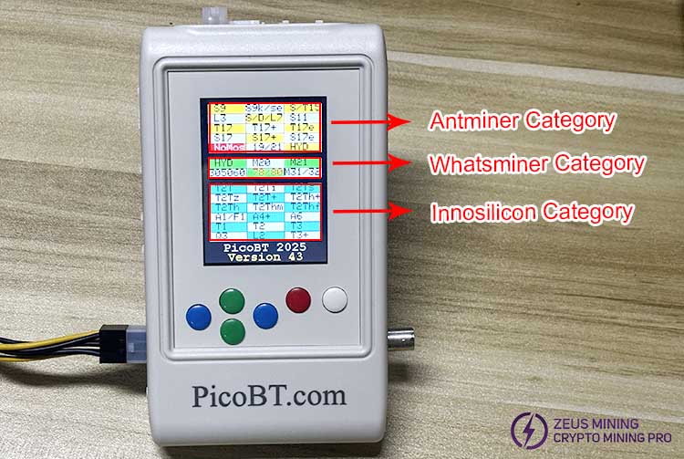
After entering the page, you will see three types of hash boards: Antminer, WhatsMiner, and Innosilicon. Use the green and blue buttons on the tester to select the type and model of hash board you need to test.
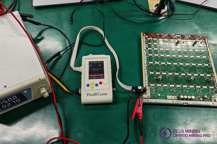
A: Regarding Antminer hash board testing, we will use the S19KPRO as an example:
This is a schematic diagram of the hash board test connection:
This is a schematic diagram of the test results:
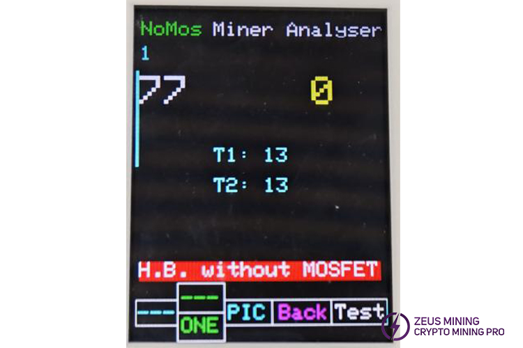
1: Represents the number of hash board tests
77: Represents the number of healthy ASIC chips
0: Represents the number of healthy chips detected from the last ASIC to any chip connected via the oscilloscope probe's test points (RI/RO/RX signals).
Note: The positive terminal of the oscilloscope probe must be connected to the RI/RO/RX signal of any chip, and the negative terminal of the oscilloscope must be connected to the negative terminal of that chip.
T1: Represents the test result of the air inlet temperature sensor chip
T2: Represents the test result of the air outlet temperature sensor chip
ONE: This is the hash board test mode switch. ONE means testing only once; pressing this button will show 999, which means automatic repeated testing.
PIC: It is recommended not to select this option, as it has already been set at the factory.
BACK: Represents returning
TEST: Represents starting the test
B: Regarding the Whatsminer hash board test, we use the M32 as an example:
This is the hash board test connection diagram:
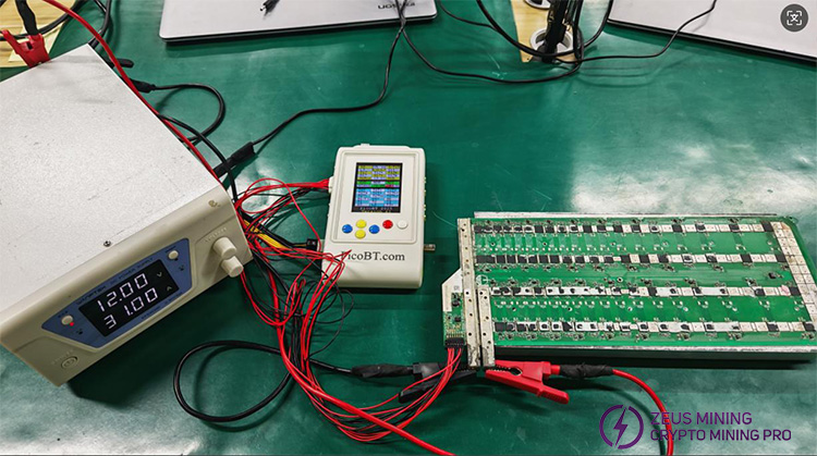
This is a schematic diagram of the test results:
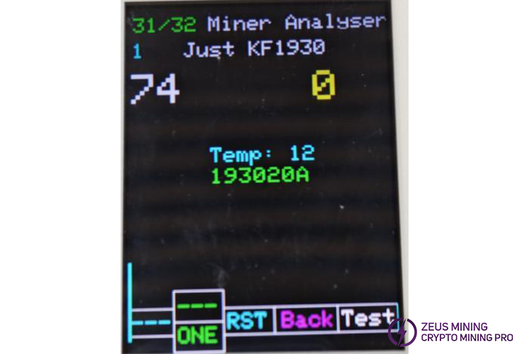
1: Represents the number of hash board tests
74: Represents the number of healthy ASIC chips
0: Represents the number of healthy chips detected from the last ASIC to any chip connected via the oscilloscope probe's TXD signal test point.
Note: The positive terminal of the oscilloscope probe must be connected to the TXD signal of any chip, and the negative terminal of the oscilloscope must be connected to the negative terminal of that chip.
TEMP: Represents the temperature sensor chip test result
193020A: Represents the ASIC chip model
ONE: This is the hash board test mode switch. ONE means testing only once; pressing this button will show 999, which means automatic repeated testing.
RST: Represents the RST signal voltage switching button. It can switch between 0V and 1.8V to test the health of the RST signal.
BACK: Represents return
TEST: Represents start testing
III. PSU tester operation guide
PicoBT tests the power supply output voltage without requiring any computer equipment. This test uses the Antminer APW12 as an example.
This is a diagram showing the cable connections:
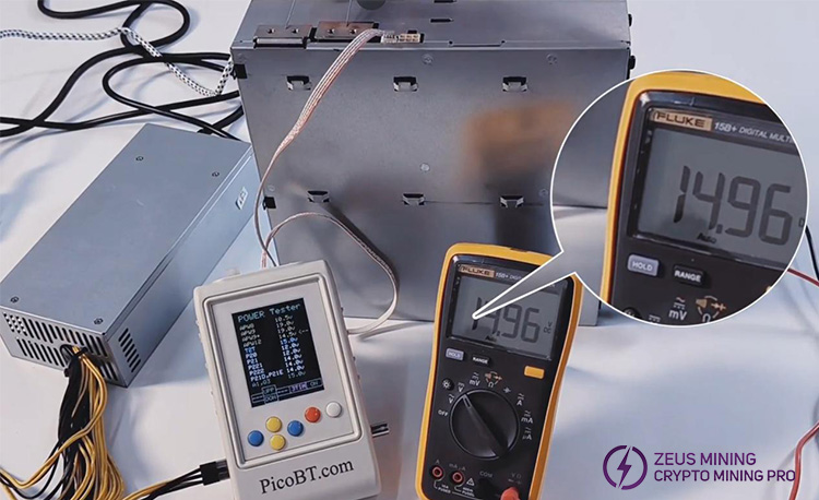
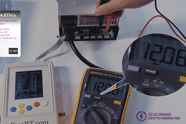
1. Connect all cables
1) Connect the 6P power cable to the PicoBT;
2) Connect the 4P regulated line to the PicoBT;
3) The 6P power cable and 4P stabilized voltage cable are connected to the APW12.
4) Connect the 220V power cord to the APW12 to supply power to it.
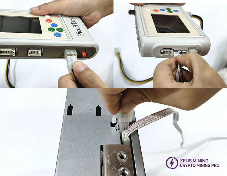
2. PicoBT enters power mode
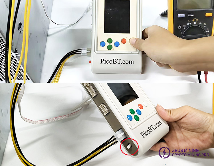
1)First,press and hold the white button, then press the switch on the left side of the PicoBT.
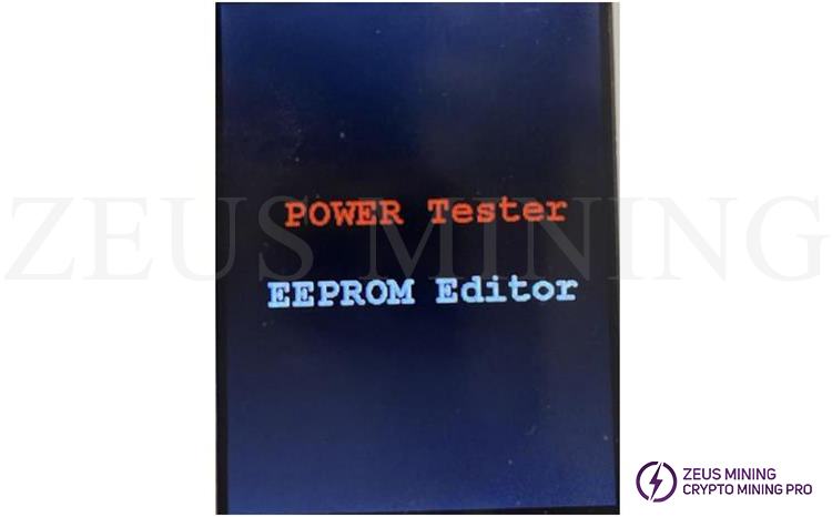
We will see a new page like this:
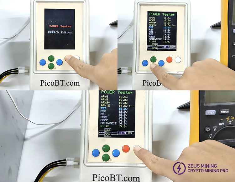
3. Select the power model
1) Press the orange button to view all power models that the PicoBT can test.
2) Select APW12 using the green button, then press the white button to start the test.
4. Perform the test
1) Switch the multimeter to the DC voltage range and press the white button on the PicoBT to start the test.
2) Connect the positive and negative leads of the multimeter to the positive and negative terminals of the power supply, respectively. The multimeter reading should be approximately 15V.
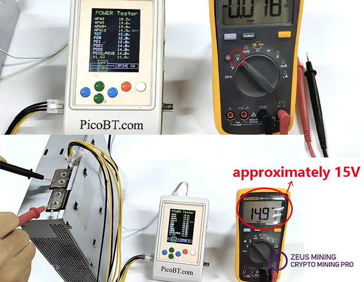
Note: We can enable all Innosilicon PSUs by selecting the "T2T15.0v" option.
Copy, flash, and save EEPROM content for Whatsminers and Antminers; we can permanently save 4 EEPROM data in the PicoBT tester.
This is a diagram showing the cable connections:
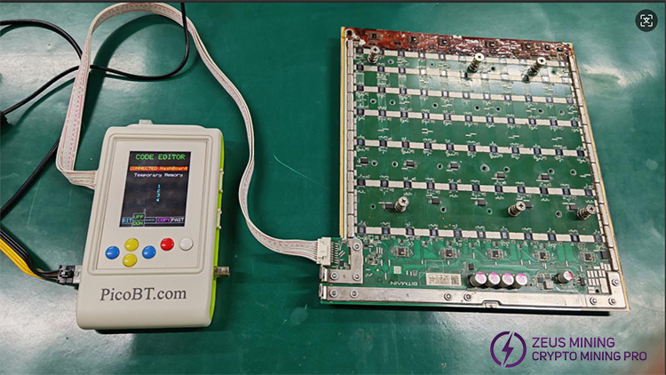
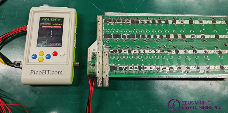
To enter the EEPROM editor, connect the input voltage cable to the tester (the On/Off switch must be closed). Press and hold the white key for 2 seconds to turn on the switch. We will see a new page on our display, as shown below:

Now press the white key to enter the EEPROM editor. Below we will see the following EEPROM editor page:
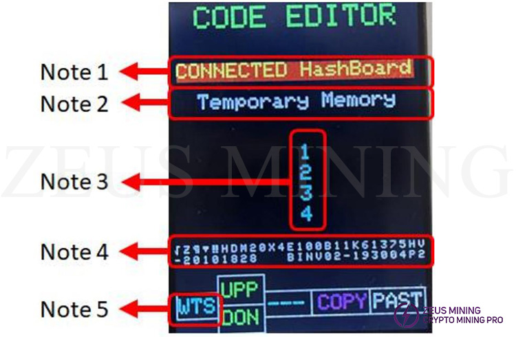
Note 1: If a connected hash board is selected, (past) data can be copied or programmed to the hash board connected to the tester.
Note 2: Any data copied from the hash board or the data of the 4 permanent memories will be temporarily saved in the temporary memory.
Note 3: There are 4 permanent memories on the tester; we can save 4 EEPROM data in these memories.
Note 4: Any data we copy from any option will appear here.
Note 5: We should choose WTS or BIT option by pressing this blue key. If the hash board is "Whatsminer," choose WTS; if the hash board is "Antminer," choose BIT.
We can select a memory by pressing the green key on the tester, the red key to copy the content of any selected memory, and the white key to paste the content of any selected memory.
Please follow the steps below to correctly activate the PicoBT test fixture:
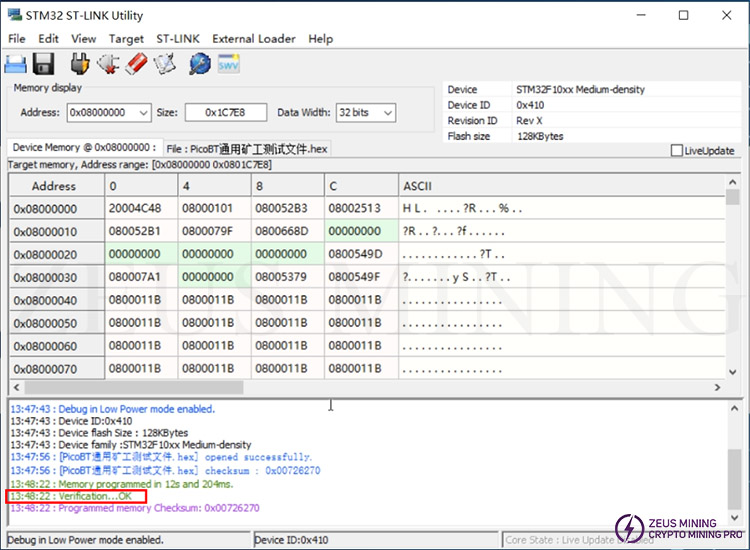
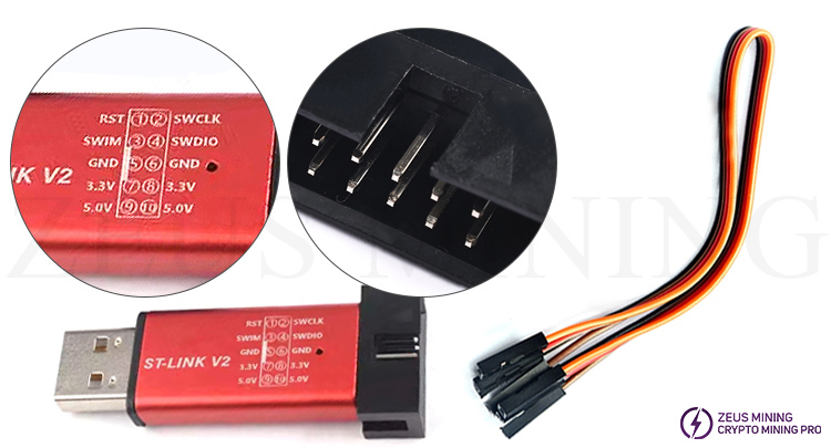
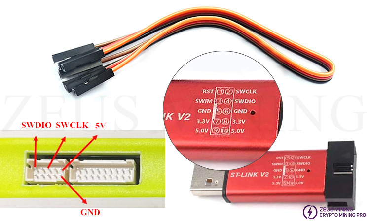
1.Insert one end of the DuPont cable into "② SWCLK", "④ SWDIO", "⑤ or ⑥ GND", "⑨ or ⑩ 5.0V" of the programmer.
2. Insert the ST-LINK V2 programmer into the computer, and then connect the other end of the Dupont cable to the SWDIO, SWCLK, GND and 5V pins of the test fixture.
3. Download the STM32 ST-LINK Utility software and install it on the computer.

4.Click the icon![]() on the STM32 ST-LINK Utility software to start connecting the test fixture.
on the STM32 ST-LINK Utility software to start connecting the test fixture.
5.Click the icon to start loading the new firmware (with Hex format)
6.Click the icon to start programming. When "OK" appears on the interface of the STM32 ST-LINK Utility software, it means that the test fixture has been successfully activated. At this time, the tester will also restart.
