


Avalon PSU3300-01 PLUS1 power supply is used in the AvalonMiner 1066 series and 1166 series. To help and guide Avalon operation and maintenance personnel to effectively improve the efficiency and accuracy of repairing faulty power supplies and reduce losses caused by downtime, we have compiled and shared the Avalon PSU3300-01 PLUS1 PSU repair manual for reference only.
1. Maintenance tools and materials
Repair tools | Specifications | Power |
Soldering iron | 150W | |
Hot air gun | 1000W | |
Absorb gun | / | / |
Tweezers | / | / |
Brush | / | / |
Long nose pliers | / | / |
Pliers | / | / |
Multimeter | / | / |
Wire stripping pliers | / | / |
Electric screwdriver | / | / |
Diameter of 0.8mm | / | |
Screwdriver | / | / |
Discharger(light bulbs) | 150W | / |
Make protective switch materials | ||
Material | Specifications | Number |
Air switch | 6A | 1 |
AC switch | 30A | 1 |
220v light bulb | 150W | 1 |
2. Power supply parameters/specifications
Model: PSU3300-01 PLUS1
Input voltage: 200-285Vac 50/60Hz 16A Max.
Output voltage: 11.5V-14.5V⎓ 3100W
12V ⎓ 200W
3. PSU basic component knowledge
3.1 Resistor
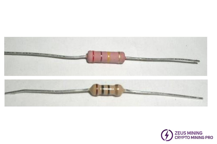
3.1.1 Carbon film resistor
Power: 1/16W~2W
Resistance value: 1Ω - 3.3MΩ
Tolerance: ±1%(F) - ±5%(J)
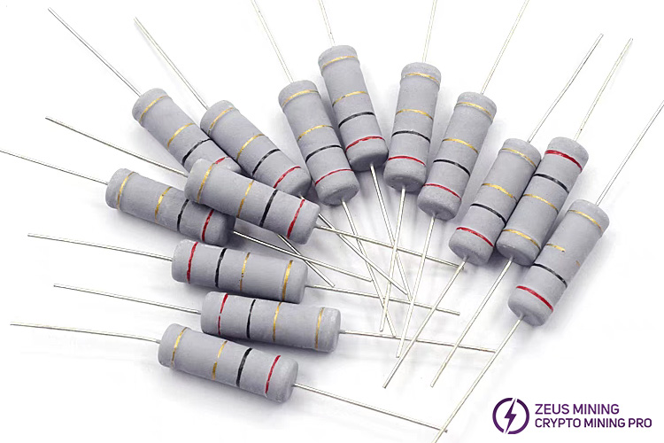
3.1.2 Metal oxide skin film resistor
Power: 1/8W~5W
Resistance value: 5Ω -1MΩ
Tolerance: ±0.1% - ±5%(J)
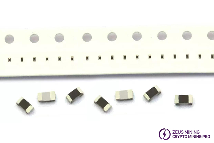
3.1.3 SMD resistor
Power: 1/16W~1/2W
Resistance value: 0Ω - 33MΩ
Tolerance: ±5%
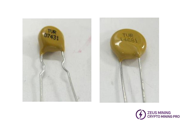
3.1.4 Varistor(safety gauge)
It has non-linear volt-ampere characteristics and is mainly used for voltage clamping when the circuit suffers from overvoltage, absorbing excess current to protect sensitive devices.
3.2 Capacitor
3.2.1 Ceramic capacitor
Withstand Voltage: depending on specific specifications
Nominal capacitance: subject to specific specifications
Tolerance: depending on specific specifications
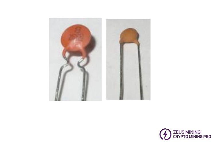
3.2.2 X capacitor: Safety capacitance
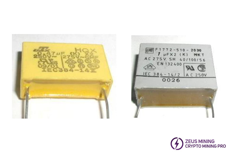
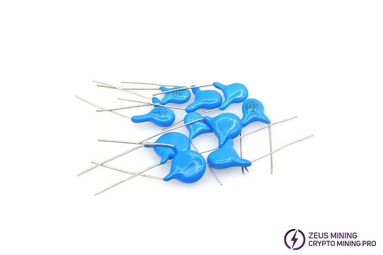
3.2.3 Y capacitor: Safety capacitance
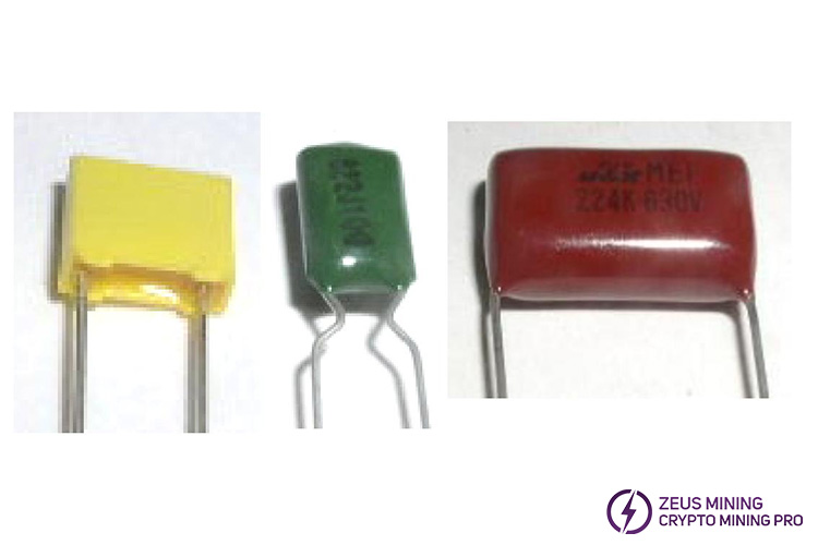
3.2.4 Thin film capacitor
non-polar
High insulation resistance
Wide frequency response range
3.2.5 Electrolytic capacitor
Polarity requirements: the long lead is positive, the short lead is negative.
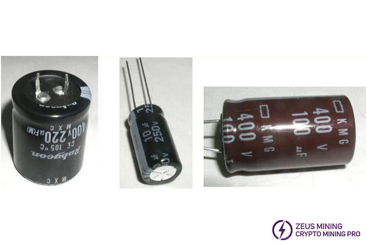
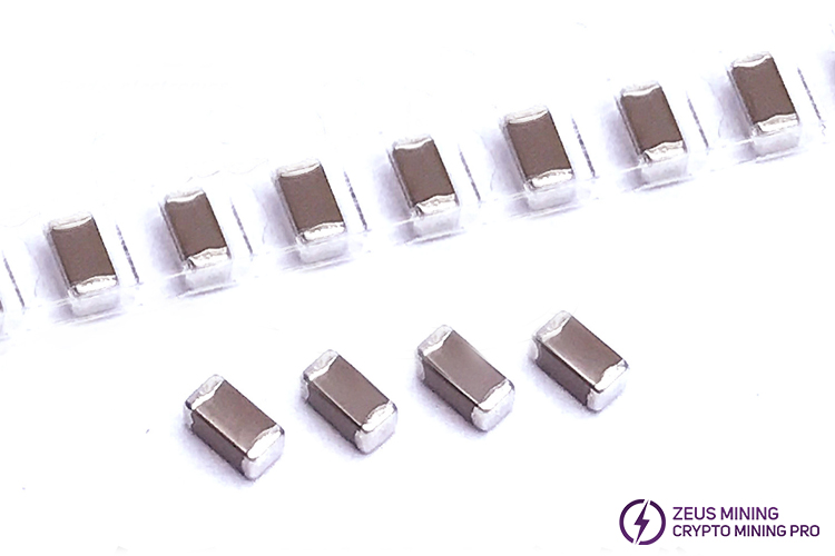
3.2.6 Patch capacitor
Pressure resistance: depending on specific specifications
Nominal capacitance: subject to specific specifications
Tolerance: depending on specific specifications
3.3 Transistors
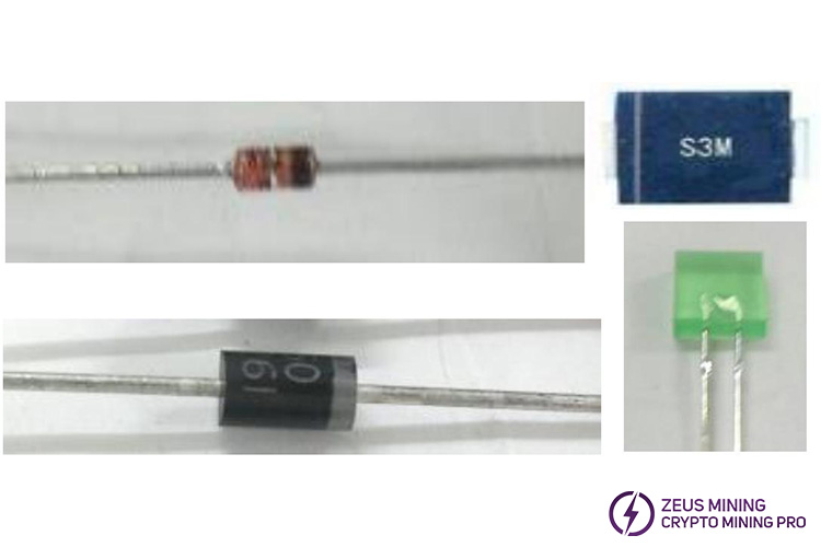
3.3.1 Diode(rectifier,switch,voltage regulator, etc.)
Polarity requirements: ring mark or short pin for the negative pole.
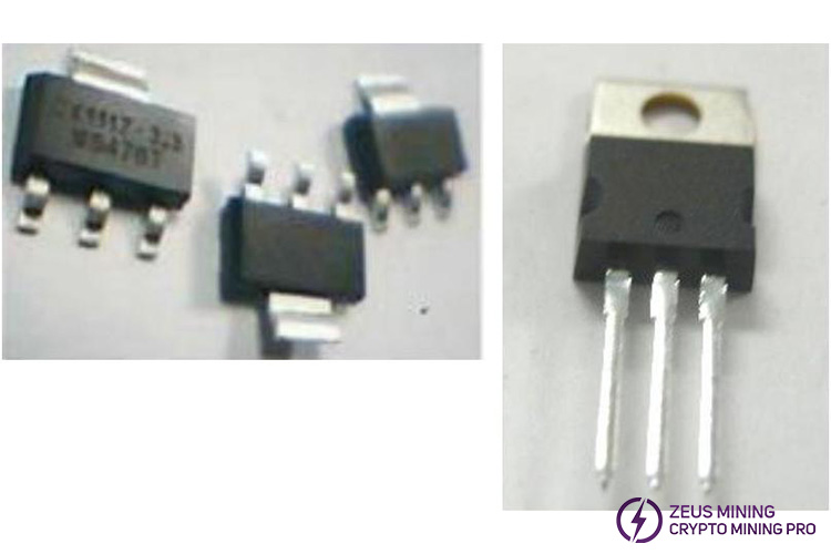
3.3.2 Triode
The main function is signal switching and amplification.
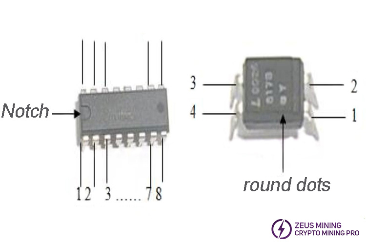
3.3.3 IC (integrated circuit)
PIN identification: Face the letters and codes on the front of the IC to yourself, so that the positioning mark (a dot or notch on the package surface) faces the lower left. The pin at the bottom left is pin 1, and the other numbers are arranged in counterclockwise order.
4. PSU working principle
The main circuits of the power supply are the EMI circuit, bridge rectifier, power correction circuit, flyback circuit, auxiliary half-bridge LLC resonant circuit, auxiliary synchronous rectifier filter circuit, main half-bridge LLC resonant circuit, main synchronous rectifier filter circuit, MCU control circuit, protection circuit.
(1) The AC power passes through the EMI circuit and bridge rectifier circuit to convert the AC power into DC power;
(2) DC power is generated through a flyback circuit to generate 18VCC;
(3) 18VCC is converted to power the relay, auxiliary circuit LLC2 IC, main circuit LLC1 IC, and PFC IC;
(4) After the PFC chip works, the PFC voltage is boosted, and the main output LLC1 and auxiliary output LLC2 IC work;
(5) After the main output LLC1 chip works, there is a main output voltage through LLC resonant circuit, and then the synchronous rectification works;
(6) After the auxiliary circuit LLC2 IC works, there is a auxiliary output voltage through LLC resonant circuit, and then the synchronous rectification works;
(7) The auxiliary voltage is translated to supply MCU IC, Which provides software communication, control, protection function.
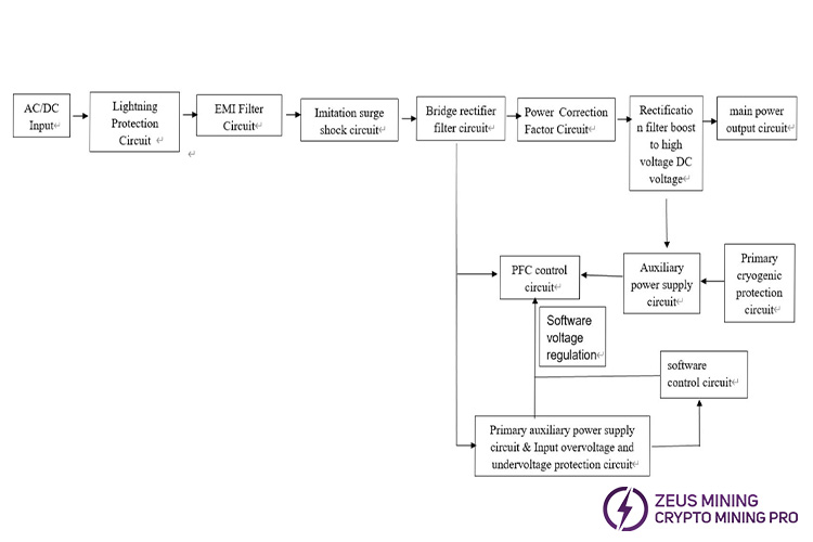
5. Power Circuit Block Diagram
6. Common troubleshooting and repair
6.1 PSU whole machine repair judgment
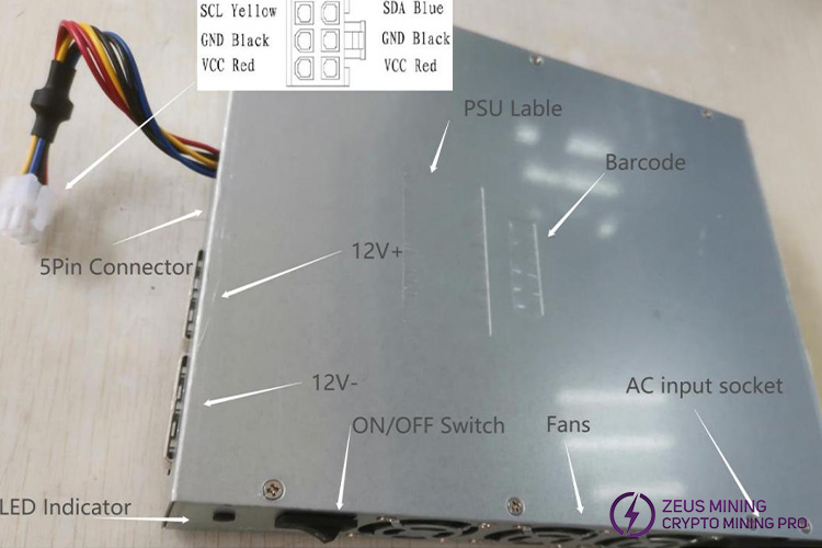
6.1.1 Product appearance
6.1.2 Product inspection and testing
(1) First observe the appearance to see if there is any obvious damage. If there are obvious appearance problems, it may have been hit or dropped.
(2) Secondly, shake it to see if there is any abnormal sound. If there is any abnormal sound, the power tube may be blown;
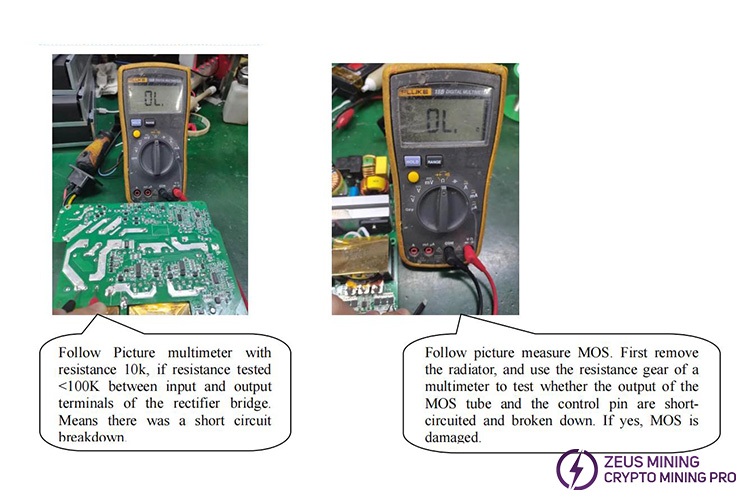
(3) Next, use a multimeter to measure the impedance of the input and output to see if there is a short circuit:
a. Whether the input terminal is loose or arcing, whether there is a short circuit between L/N/G;
b. 12V main circuit output terminal deformation, short circuit with the shell, short circuit measurement between positive and negative poles;
c. The 12V auxiliary circuit output terminal is damaged, short circuit between PINs, short circuit measurement between positive and negative poles;
(4) Check whether the fan blades are blocked by foreign matter;
(5) When the PSU is powered on, short-circuiting the AGND and SETUP of the 5Pin terminal can activate the main circuit output;
(6) Observe the panel indicator light. The green light is on during normal operation. The red light indicates abnormality and the input voltage needs to be disconnected immediately.
(7) Turn on the power supply and observe the internal indicator lights:
a. The indicator light is always on: the output fan is faulty;
b. The indicator light flashes once and goes off for 3 seconds: protection for excessive ambient temperature;
c. The indicator light flashes 2 times and goes off for 3 seconds: secondary heat dissipation temperature protection;
d. The indicator light flashes 3 times and goes off for 3 seconds: LLC heat dissipation temperature protection;
e. The indicator light flashes 4 times and goes off for 3 seconds: PFC heat dissipation temperature protection.
(8) If there is no response after powering on, open the cover and discharge the capacitor.
a. Turn on the input control switch (0: off, 1: on), and measure whether the switch is closed normally;
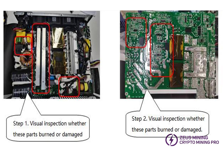
b. Observe whether there are any burned components inside the power supply;
c. Measure the main power tube to see if there is any damage.
(9) Bare metal power on: Measuring key voltages
a. Large electrolytic capacitor voltage: about 390V;
b. Primary auxiliary circuit VCC power supply: about 15V;
c. Auxiliary output power supply: 15V;
d. Auxiliary circuit: 12V
e. Main circuit default output: 13V
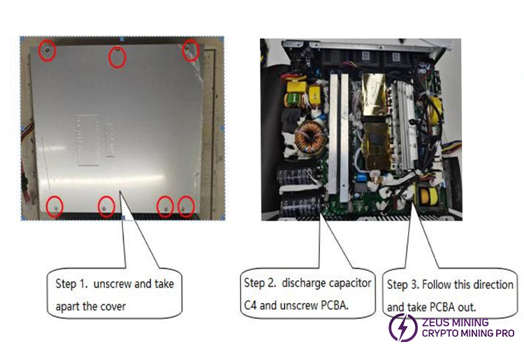
6.1.3 Flowchart of disassembling the casing
6.1.4 PCBA appearance defect judgment
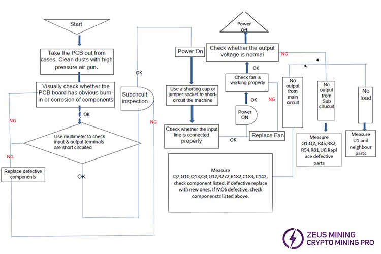
6.1.5 PCBA hardware fault analysis flow chart
6.1.6 Use multimeter to detect faults
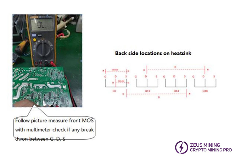
6.2 Common fault analysis and repair
6.2.1 List of common faulty devices
Item | Failure | Location | Main defective Parts | Parts to Diagnosed |
1 | PFC voltage no 390V | PFC circuit | TR1 short circuit | F2, RB1, RB2, RT1, D5, D9, D13, Q32, Q33, Q34, R311, R309, R314, R329, R330 some of these parts fail |
2 | PFC voltage no 390V | PFC circuit | C4, C24 fail | / |
3 | No output | 13V main MOS drive circuit | Q10, Q13, Q3, Q7 shortcircuit | Some components of U7, U19, U12, RT1, D5, D9, D13, R329, R330 failed |
4 | No output | 12V output MOS drive circuit | Q1, Q2 shortcircuit | Some components of U6, Q21, Q23, R53, R56, R87, R110 failed |
5 | No output | 13V main output circuit | Q6, Q8, Q9, Q11, Q12, Q14, Q15, Q16, Q17, Q18, Q19, Q20 failed | Any one of them fails, short circuit between G/D/S |
6 | Main output high ripple | 13V main output circuit | C31, C32, C40, C41, C46, C47, C48, C49, C51, C52, C55, C56, C57, C59, C60, C62, C63, C64, C65, C66, C70, C71, C72, C73 | Any one of them fails and the capacitance decreases |
7 | No output | 12V auxiliary output circuit | Q22, Q24 invalid | Any one of them fails, short circuit between G/D/S |
8 | No output | Fan | The fan blades are clogged, or the fan wire is corroded and open circuit | / |
9 | No output | Input circuit | ON/OFF Switch fail | / |
10 | No output | 12V output cable | 12V output cable is damaged or fall off | / |
6.2.2 PCBA common faults and repairs
(1) No output
Step 1. check whether the C4 capacitor voltage is 388 volts to 420 volts. if no, check the circuit near U15 to see if there is 14 volts.
Step 2 . 14 volts are powered by U10, U7, U6. If normal, check whether the output MOS is short-circuited. If not, check whether the front-stage MOS tube and nearby circuits are normal.
(2) Main circuit has no output
Auxiliary circuit is normal and the main circuit has no output. Check whether the 7th pin of the communication board has 1.5 volts. If so, it means communication signal is normal. Check whether input and output MOS tubes are shortcircuited, and whether the components near U12 and U19 are normal, and whether the PFC voltage is normal.
(3) IIC communication out
First make sure that the auxiliary circuit of the machine has 12V output, and short-circuit AGND and SETUP with a short-circuit cap to start the main circuit, and the output voltage is normal, indicating that the power supply of the machine is normal.
It is necessary to check whether the output 6P cable is damaged and the wire sequence is correct. If it is correct, check whether the components around the U14 chip are damaged, and use a multimeter to connect DAT and CLK to the ground resistance value is correct.
If it is not correct, it can be judged that it is a problem with U14 and nearby circuits. If the resistance value is correct, it is necessary to check whether U17 and the nearby circuit and power supply voltage are normal. If the program is lost, it will not communicate.
(4) PSU failure
Measure C12, C17, C31, C32, C40, C41, C46, C47, C48, C49, C51, C52, C55, C56, C57, C59, C60, C62, C63, C64, C65, C66, C70, C71, C72, C73.
(5) The machine cannot be powered on
Step 1. Check ON/OFF switch fail or not.
Step 2. F1 fuse broken or not.
Step 3. C4 capacitors voltage within 388-420V.
Step 4. Measure with multimeter to check input MOS fail or not.
7. Maintenance Precautions
(1) When bad power supply is confirmed, be sure to use the protective switch to avoid explosion injury.
(2) Pay attention to electrostatic protection during maintenance, and wear an antistatic bracelet.
(3) Electric soldering iron temperature management, it is recommended to control in 380℃~420℃.
(4) When replacing materials, use products of the same model and specifications. Do not use substitute materials without permission.
(5) The defective materials that are repaired and replaced shall be marked as defective, and the on-site positioning management shall be optimized to avoid mixing with qualified products.
(6) Record the power supply S/N serial number, bad phenomenon, bad reason, maintenance method and other information, regularly provide maintenance record form.