


This hash board repair guide is suitable for Avalon Miner A1066, A1066pro, A1026, A1046, A1047, etc.
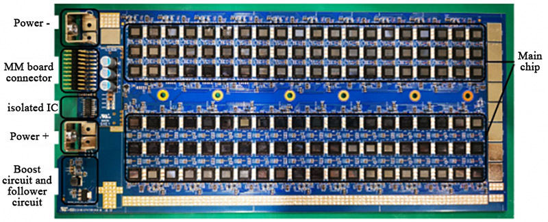
A10 series hash board introduction:
1. Positive and negative poles of the power supply;
2. Communication interface: communicate with MM board;
3. Main chip: ASIC chip;
4. Isolated chip unit;
5. Boost and follower circuit.
A10 series hash board test fixture interface introduction:
1. Connect the positive and negative poles of the Hash board power supply;
2. Connect the data cable of the hash board;
3. It is recommended to install the tooling bottom plate (insulation);
4. MM board with test script program;
5. Adjustable power interface cable;
6. USB to a serial port, connect the USB to the computer, and read the hash board test information through the serial port debugging tool.
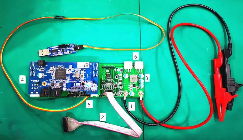
Test fixture connection method:
1. The power supply interface of the primary circuit of the power supply, in which black is the main output negative pole, and red is the main output positive pole;
2. The negative interface of the main circuit power supply of the Hash board;
3. Hash board main circuit power supply positive interface;
4. The data protocol interface of the hash board;
5. USB to a serial port, the interface is defined as:
Test fixture | USB to TTL |
TX | TXD |
RX | RXD |
GND | GND |
6. Power supply 12VSB and IIC interface (2*4 interface).
Hash board test method:
①According to the status of the indicator light of the test fixture, to determine the status of the hash board, and to determine whether maintenance is required;
· A green light indicates that the hash board is healthy and does not require maintenance.
· The red light indicates that the hash board is abnormal and needs to be repaired.
②By connecting the serial port debugging tool to the computer screen, determine whether there is a problem with the hash board;
First, set the serial port software debugging parameters: among them, the baud rate is set to 115200, the data bit is 8, and the stop bit is 1.
Through the serial port debugging tool, check the LOG information of the hash board running on the computer, as shown in the figure:
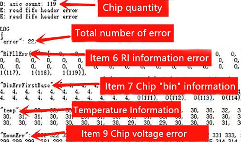
Among them, the ASIC count is 120 chips, and the test fixture is bright red, indicating that the test circuit is not working and needs to be repaired. In addition, the 9th item + 7 item + 6 item in the above figure = a total of 22 items, indicating that there are problems with these three indicators, which need to be checked and repaired.
The following figure is the error code comparison table:
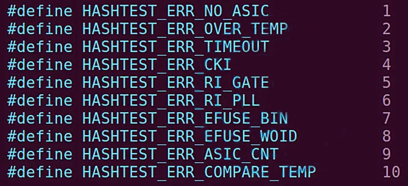
Error code description:
Error code | Describe |
1 | Failed to enumerate ASIC chips |
2 | ASIC chip high temperature (greater than 90°C) |
3 | Test timeout |
4 | CKL signal error |
5 | RI signal error in gate state |
6 | RI signal error at the configured frequency |
7 | ASIC chip BIN information error |
8 | ASIC chip batch number error |
9 | ASIC chip voltage error |
10 | The difference between the maximum and minimum temperature of the ASIC chip is relatively large |
The software can scan the chip, but if the chip is not working, the voltage entry will show 0, and a comma will appear after each voltage value.
If the software does not scan the chip voltage value, the software will automatically fill in 0. It is necessary to check the adjacent chip at the 0 positions during maintenance. Likely, the 0 positions or the adjacent chip does not work.

Hash board voltage test:
The first thing to do is test the power supply's impedance on the hash board. The resistance values are shown in the table below. If there is a short, you'll need to inspect parts of the circuit for burnout or solder shorts. After the impedance test is completed, the power-on test is performed to test the power supply voltage of the entire hash board. The test positions and test voltage values are as follows:
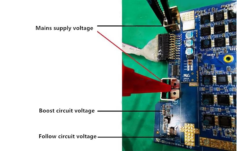
The measured position and voltage values are:
Test power | Test location | Voltage value | Impedance value |
Power voltage | "-" is in black clip & Vcore+ | 11.15V | 2Ω |
Boost circuit voltage | "-" is on the black clip and the left end of the C399 | 16.28V | ≥60kΩ |
Follow circuit voltage | "-" is at the black clip and U98 pin4 | 12.95V | ≥400Ω |
ASIC chip detection:
If the voltage test passes, the ASIC chip of the hash board needs to be tested. Take the A10 hash board as an example; there are 40 groups of chips connected in series on the hash board, each group of chips is composed of 3 chips in parallel, and each chip includes three power supplies and 4 groups of signals: Vcore, VTOP and VDDIO, the signal is: CKin, Cin, Rin, Din and CKout, Cout, Rout, Dout.
Each group of chips consists of three chips in parallel. The VDDIO and VTOP of each group of chips are powered by 1.8V-LDO and 0.75V-LDO, respectively. In addition, there will be VDDIO and VTOP test points next to each group of chips, which can test the voltage value.
as follows:
Chip voltage test, the working voltage value of each chip is: | |
Type | Voltage value |
Vcore | 280mV |
VDDIO | 1.8V |
VTOP | 0.75V |
Signal test:
When there is a problem with the hash board, it is necessary to test the chip's signal and power supply IO and TOP. This is because the chips' signals on the hash board are connected in series, the signals of each chip are CK, C, R, and D, and each chip needs to test the output signal.
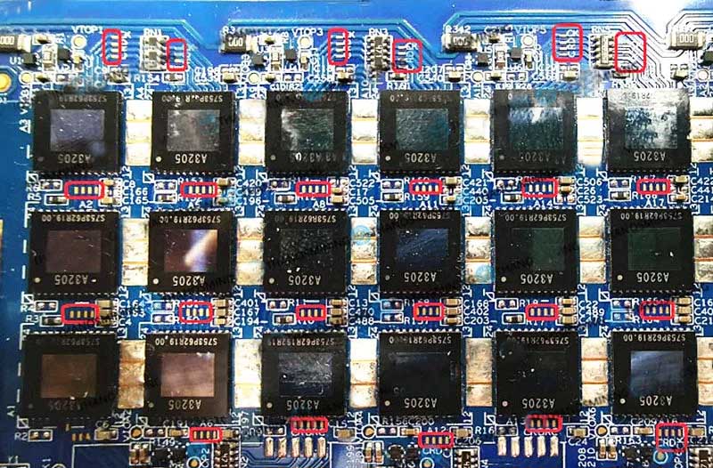
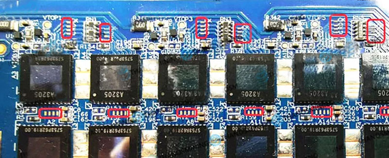
The enlarged hash board is shown in the figure below, where the red box is the test point of the ASIC chip:
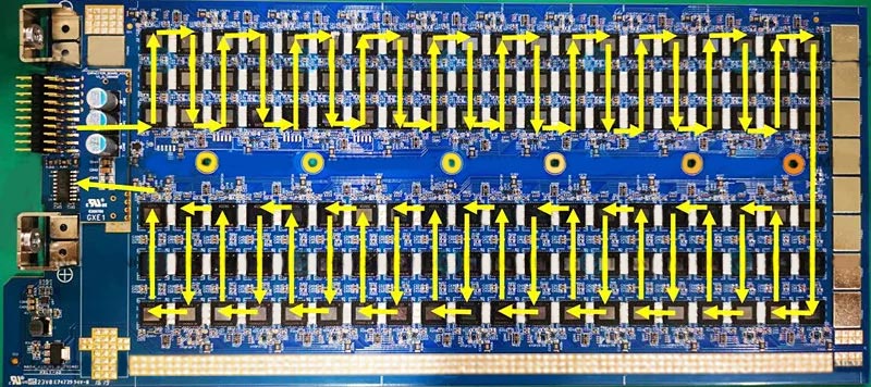
Description of the signal transmission direction of the Avalon hash board:
Each group of signals includes four signal test points, they are CK, D, R, and C;
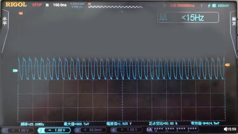
CK: Chip working clock, the frequency is 25MHz;
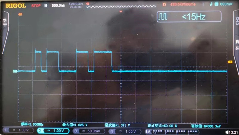
D: The transmission data signal of the chip;
R: The reset pin of the chip;
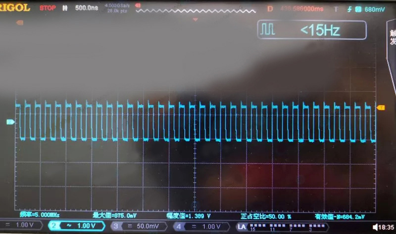
C: The transmission clock signal of the chip.
Test the waveform with an oscilloscope to determine whether the chip is abnormal:
The oscilloscope settings are AC position; amplitude is set to 1.00V/div; frequency is set to 500ns/div.
The waveform of the CK signal, the frequency is 25MHz, and the amplitude is 1.5V-1.8V;
The waveform of the C signal, the frequency is 5MHz, and the amplitude is 1.5V-1.8V;
The waveform of the D signal, the amplitude is 1.5V-1.8V
Please use a Fluke multimeter for chips with abnormal waveforms to test their voltage and resistance values. When it is determined that the ASIC chip is damaged, please replace the damaged ASIC chip by yourself.