


M3x series miners include M31S, M31S+, M30S, M30S++, M32, etc.
Tips need your attention:
1. Whatsminer m3x hash board normal working voltage is from 0.31~0.32V * No. of groups( e.g., 0.31V*37=11.47V, i.e., the input voltage is 11.5V), recommend taking this as a maintenance standard.
2. Recommend using oscilloscope instead multimeter to test clock voltage.
3. Please ensure the above correct operation; if there are any violations, which will lead to wrongly analysis and cause some unnecessary loss.
I. Product Overview


II. Maintenance Environment Building
1. Tools list
2) 936A electric soldering iron
3) Electronic hot plate preheat station
4) Customize the control board for maintenance
5) TF Card
6) 12V DC power supply for control board 12V
7) Adjustable 10A+ DC power supply
8) 100M oscilloscope
9) Multimeter
10) Gloves
11) Tin paste
12) Solder Paste
13) Power cord, network cable
14) Cable
15) Tweezers
16) Computer
17) Electrostatic table
18) M1 miner case with a fan
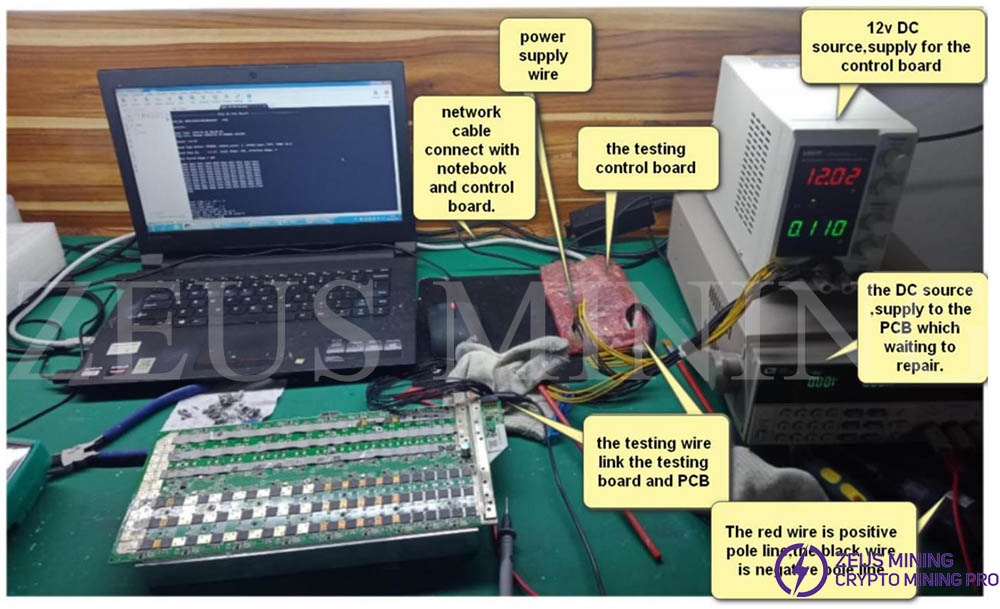
2. Hashboard testing software
M3x is the same as M20S, tools as below.
III. Hashboard Block Diagram Brief Introduction
M3x block diagram is the same as the M20S (refer to M20S Repair Guidance). The circuit consists of a group chipset, temperature sensor, boost circuit, memory, and voltage level conversion. The difference is the hash board with 1 pcs of the crystal oscillator; each group LDO supports 2 group * 1.8V & 1 group * 0.8V.
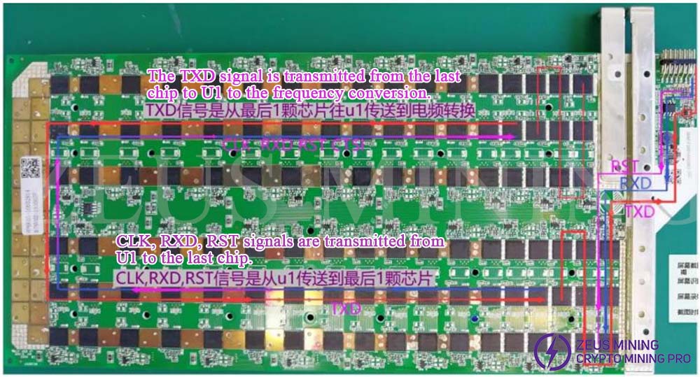
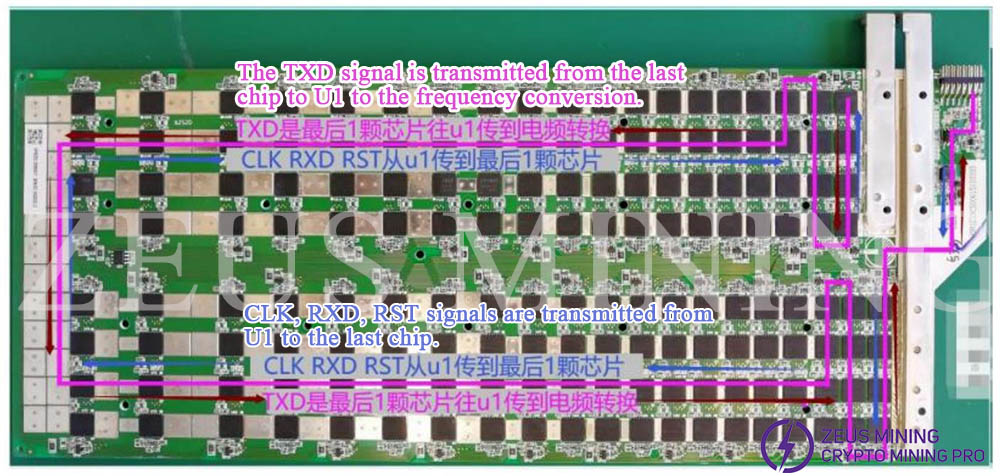
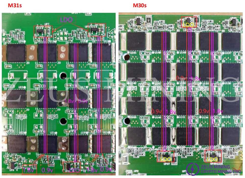
1. General signal transmission direction picture as below:
M31S:
M30S:
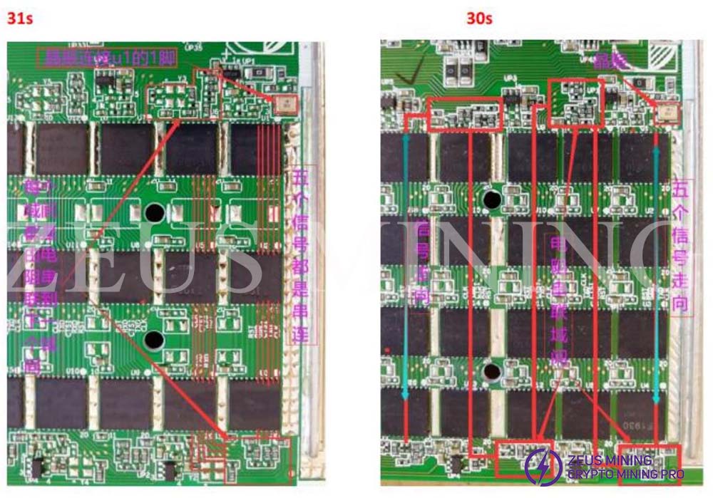
2. M3x hash board has a 1PCS crystal oscillator; the signal between the two groups were connected by resistance.
3. Each group's LDO 1.8V support Pin 7 Pin 8 Pin 13 Pin 14 voltage input and 0.9V support Pin 6 Pin 15.
4. 17V boost circuit
As a highlight in red, 17V is for the last 8 groups.
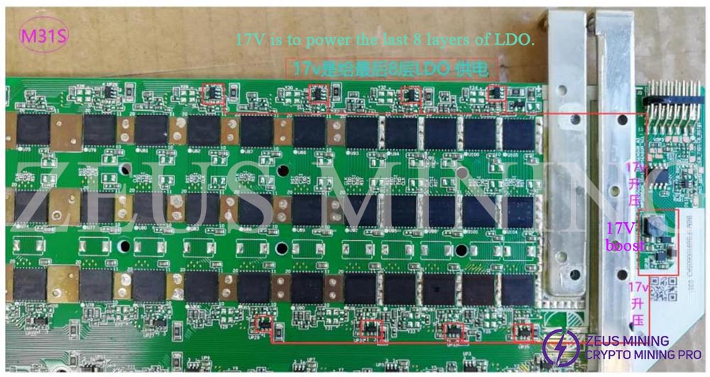
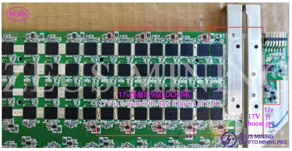
Tips: This 17V is for the last 9 groups based on the hash board version.
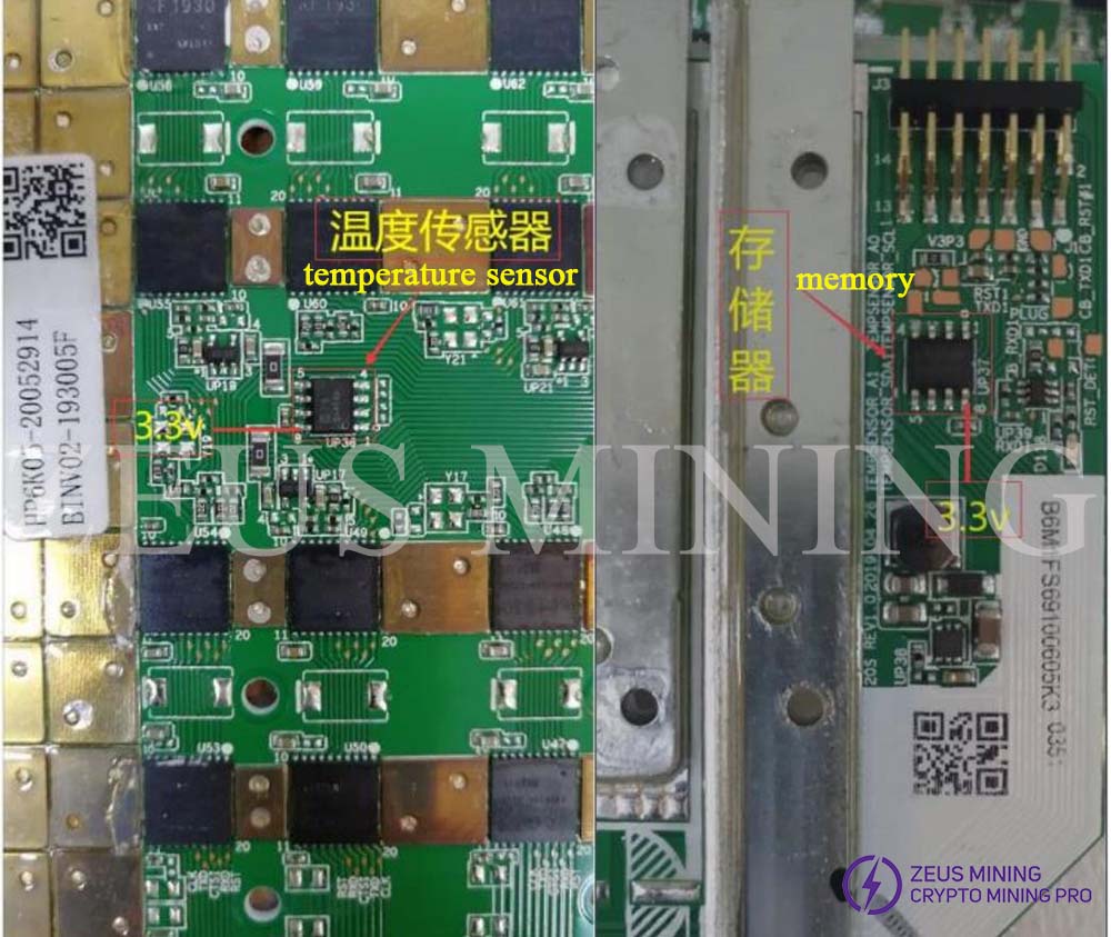
5. 3.3V is for temperature sensor and memory
The left arrow refers to the temperature sensor. The right arrow refers to the memory.
6. Voltage level conversion is between 3.3V and 1.8V.
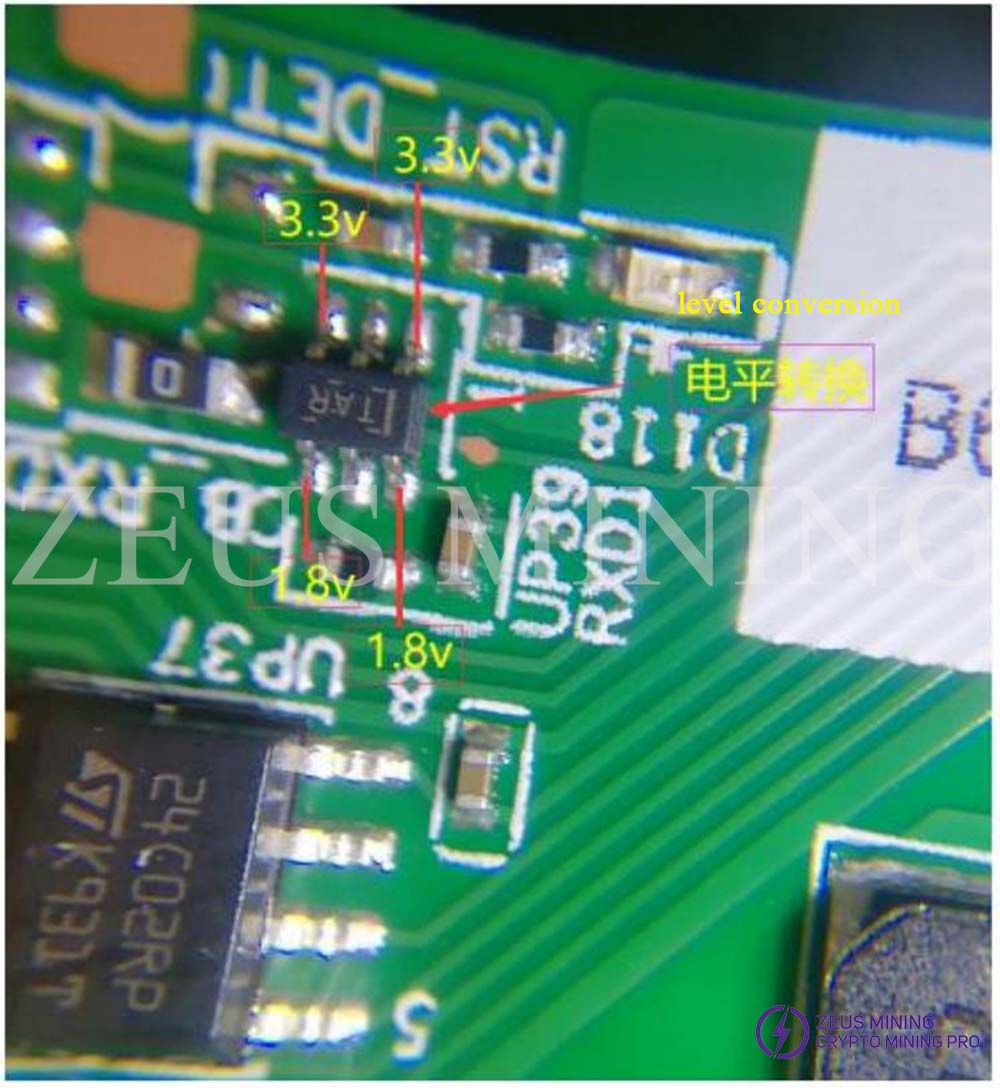
IV. Case Study
The sequence of maintenance, start from RST-> CLK->RXD->TXD.
Please must use an oscilloscope to test CLK voltage; 0.15V is normal working.
Any error code needs to check daily log.
Case1: M31S delivers error code 542, can’t read hash board, as below picture.
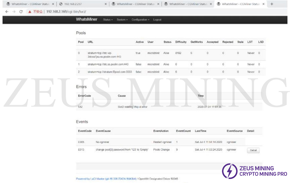
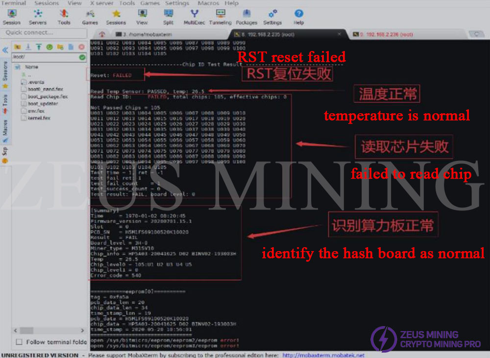
Remove the SM2, test by platform, and it is said RST failed.
4 red arrows : RST failed-> temperature normal-> read chipset failed-> read hash board normal.
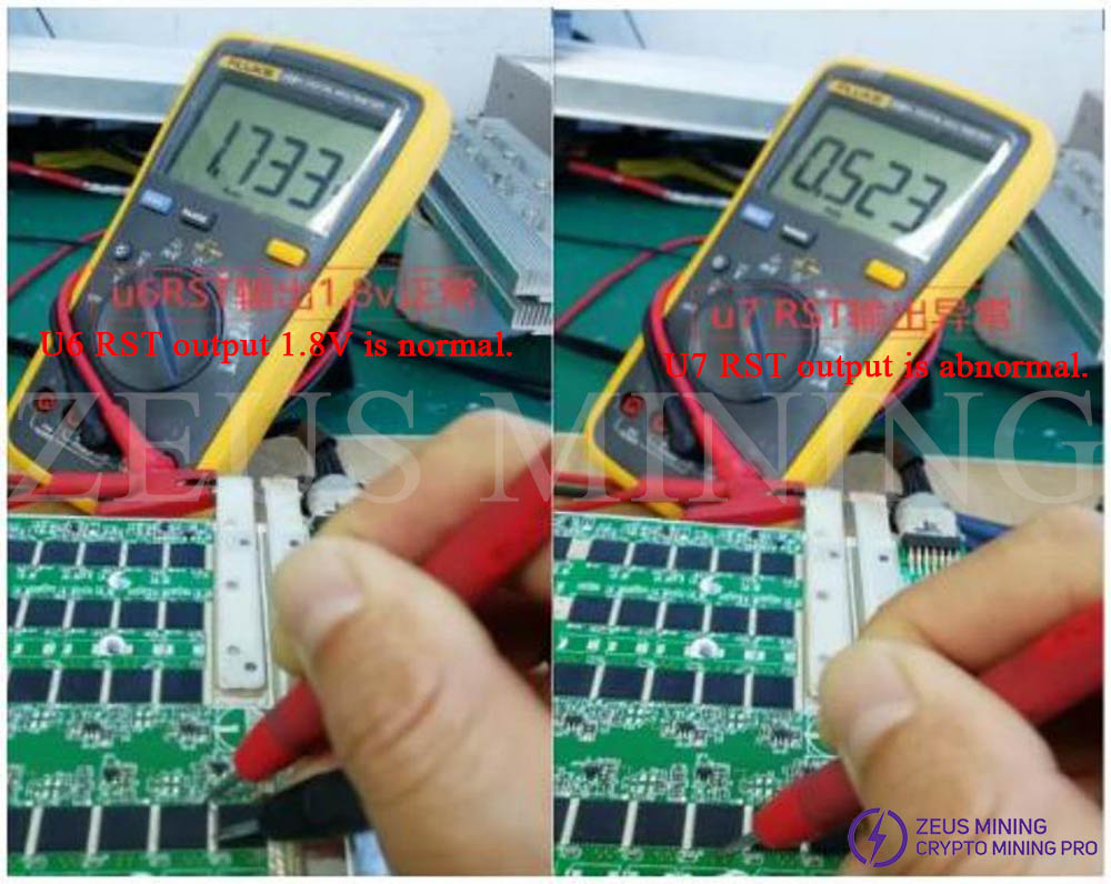
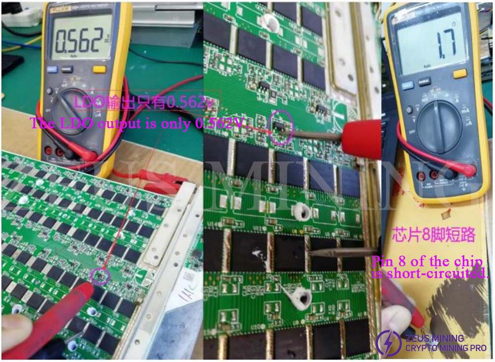
According to the basic maintenance rule, the first step to measuring RST, use the software typo command echo 1 > /sys/class/gpio/gpio99/value (if this command is invalid, use echo 1 > /sys/class/gpio/gpio197/value) to improve the level converter, measure the RST dot one by one, Find U6 RST output 1.8V, U7 RST output 0.5V not 1.8V, as below picture.
After measuring group by group, it was found that failed on 3rd group, LDO output is 0.56V; after further measure, found the pin 8 of U8 is 1.7Ω, it was a short circuit, caused LDO output voltage lower.
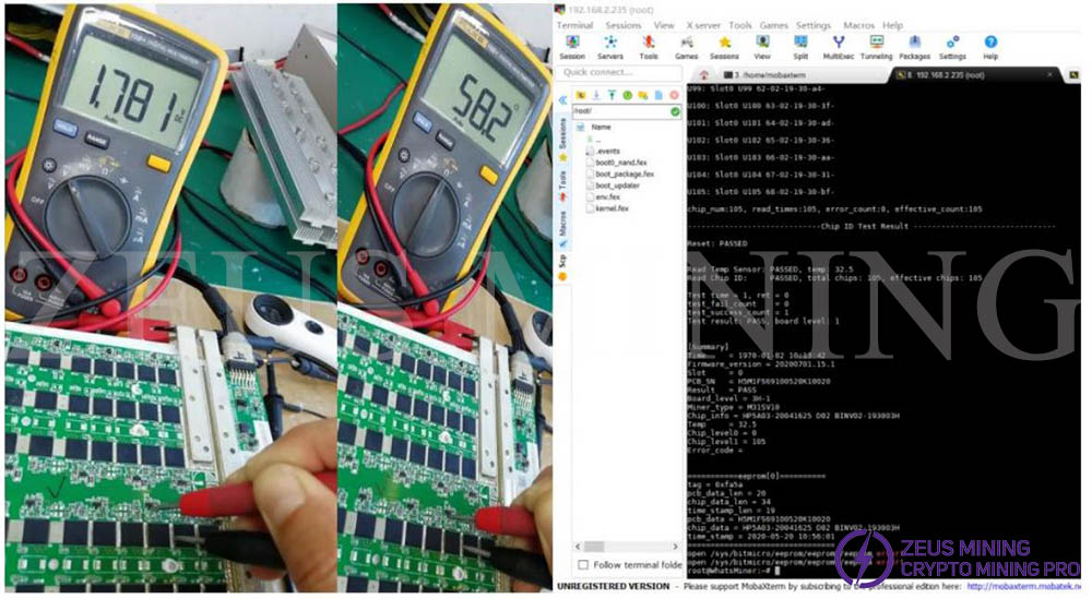
Replaced U8, LDO output shows 1.8V, normal working, electrical resistance to earth shows 58Ω, normal working. The software test result is PASSED, as below picture.
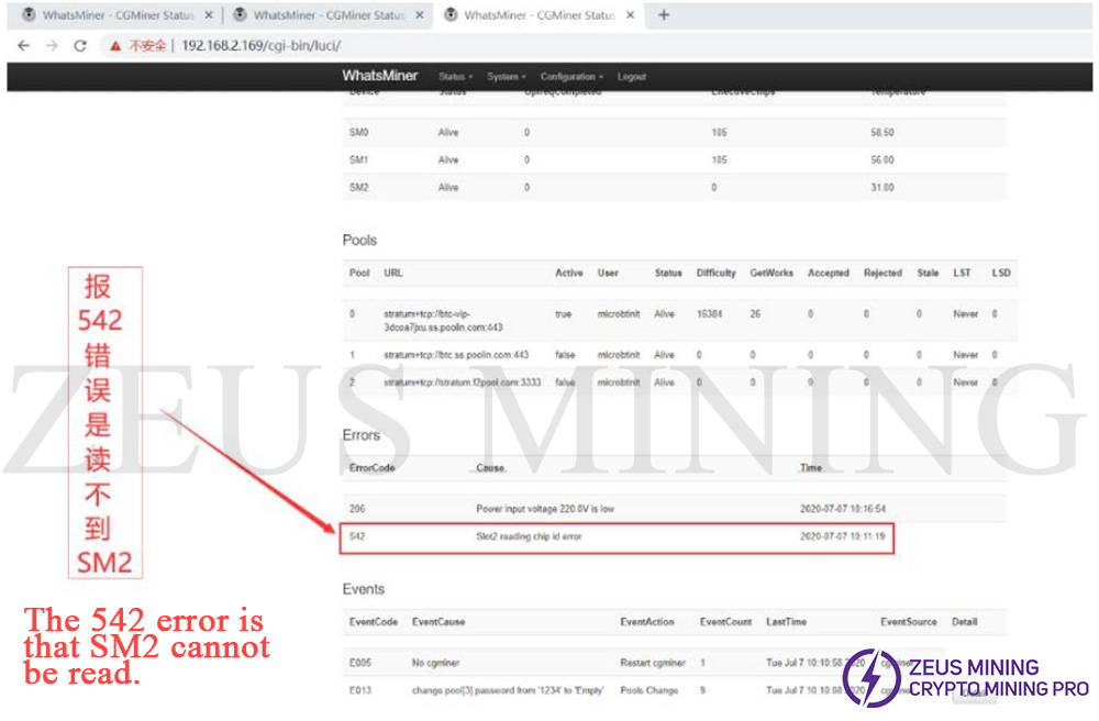
Case 2: M31S error code 542 means can’t read SM2.
IP screen:
Remove SM2, test it with software; it showed a total of 104 chips, missing 1 chip called U9.
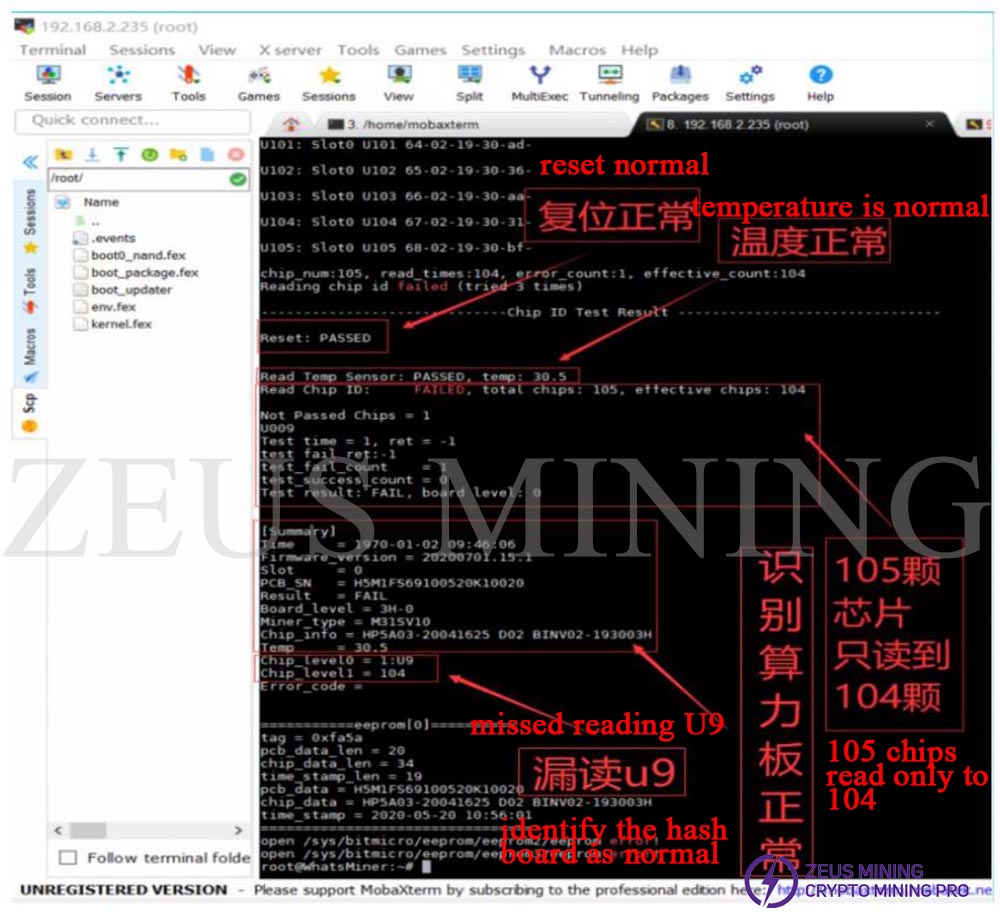
Solution: Remove the radiator, change the U9 chip, test via software; it was successful, install it into the miner, and do the aging test.
Attention: must check the right sequence of the chips. Some printing on the chips may not 100% match the position.
Case 3: M31 Error code 561, 562, failed reading SM1, SM2.
IP screen as below:
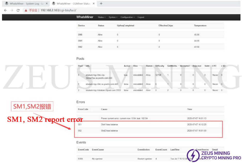
After connecting, the miner rebooted and exported the daily log to check if it was the power supply issue. Exporting log instructions:
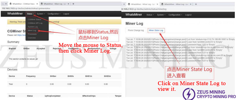
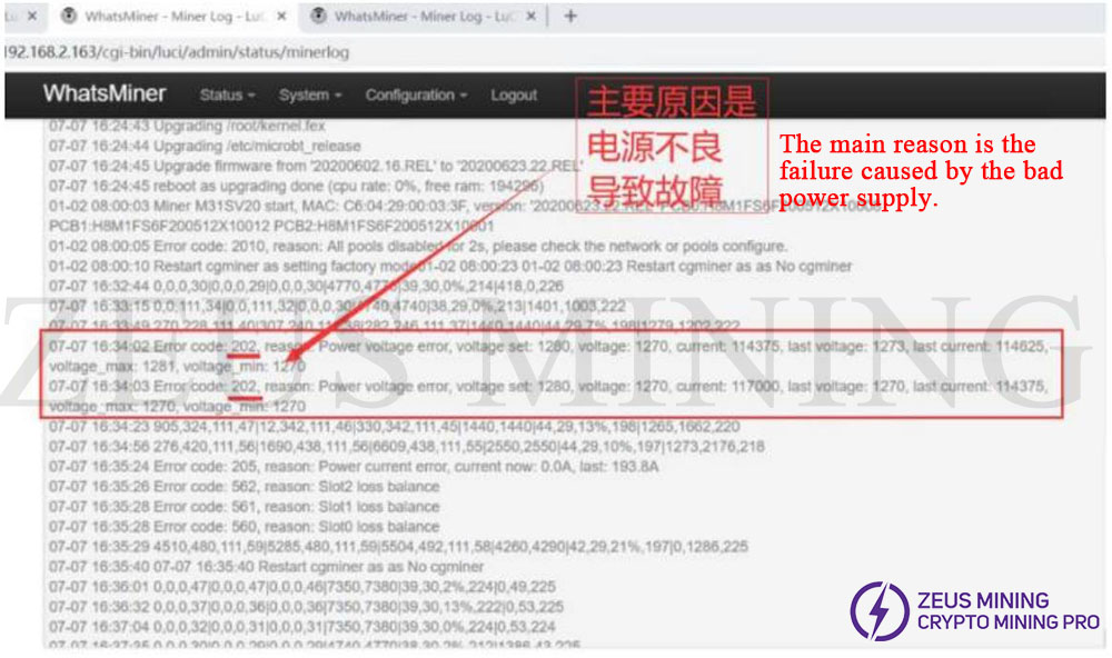
After analysis, confirmed error code 202 was power supply failure, which caused miners to fail.
Cace 4: M31+ Error code 540, SM0 chips reading failed.
IP screen:
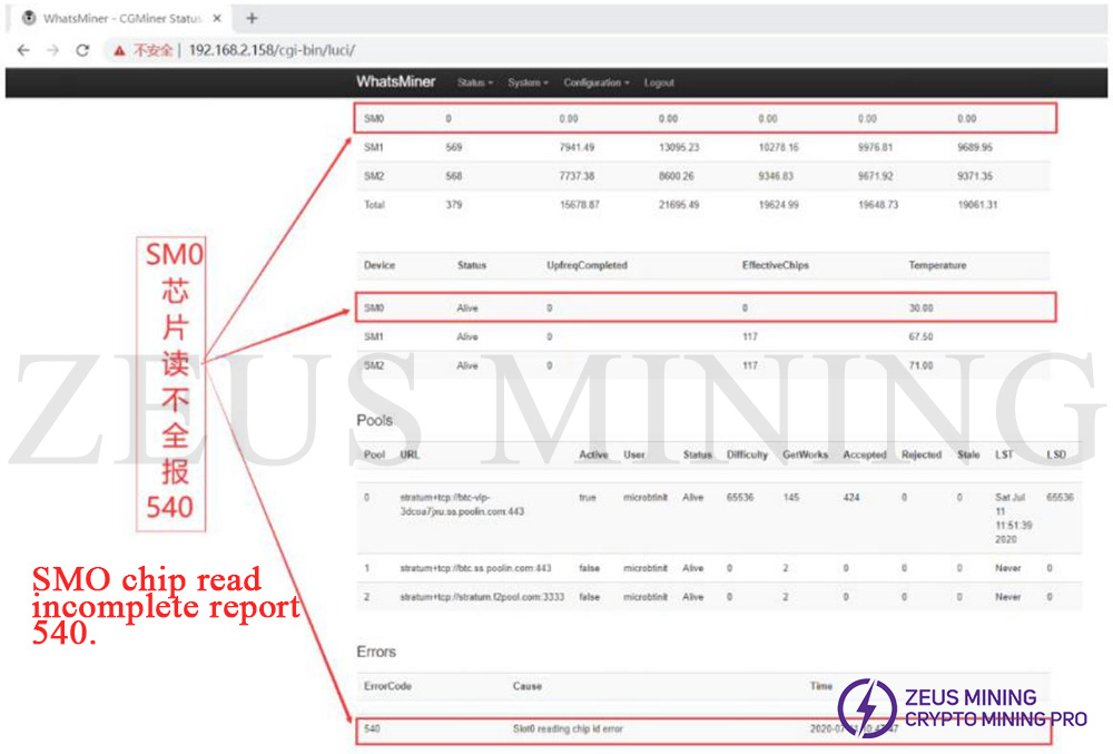
After the test via software showed that U109, U119, and U111 chips reading failed.
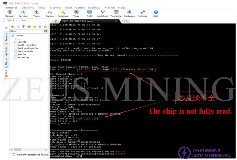
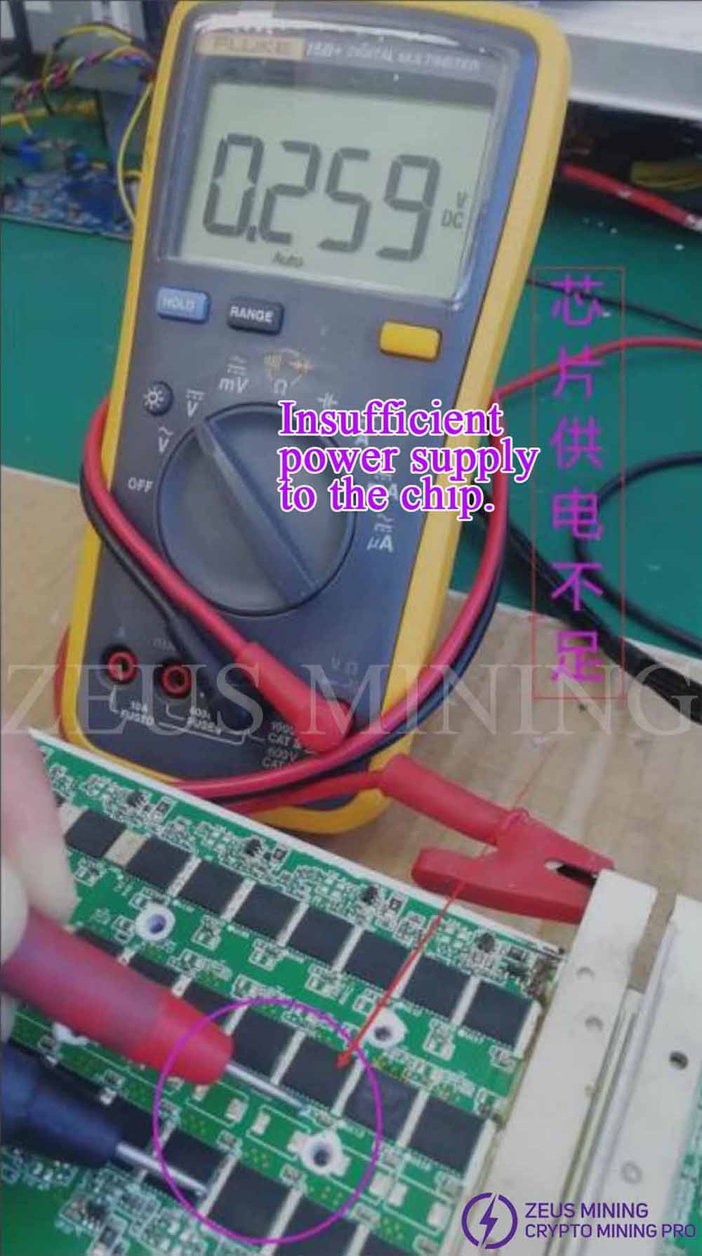
The group chipset found a 1.8V shortage after further checking the U110 circuit.
Replaced U110, installed to the miner, and did the aging test.
Case5: M30S error code 530 means it can’t detect SM0.
IP screen:
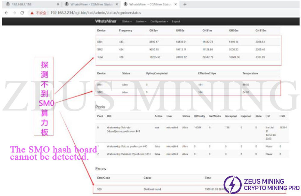
It was found that the fan was damaged and vibrated, which led to the looseness of the cable. Plug in the cable again, and the power on the test is OK.
Case 6: M30S error code 236, 255, 268, the main reason was the failure of the power supply.
IP screen:
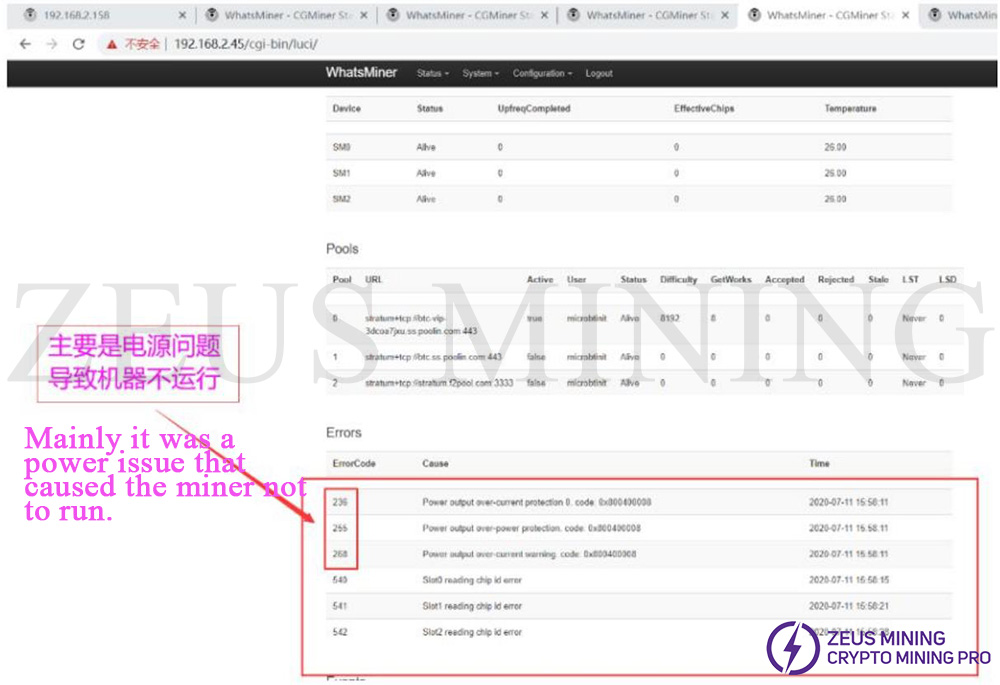
The power supply caused this kind of error code. Replace the power supply and test the normal operation.
Case 7: M30S shows error codes 250, 25, 540, 541, and 542.
IP screen:
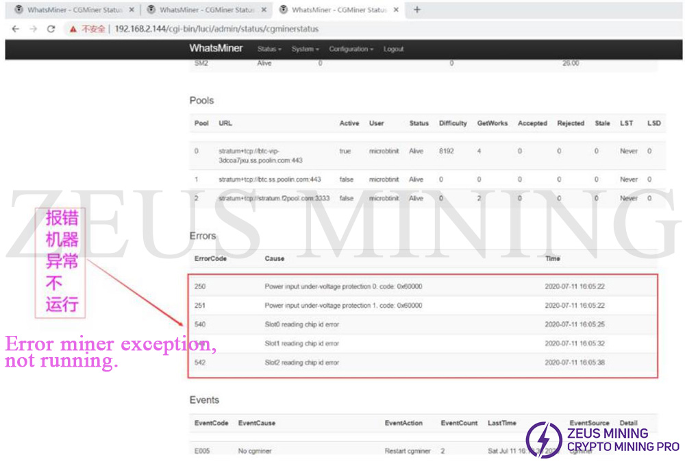
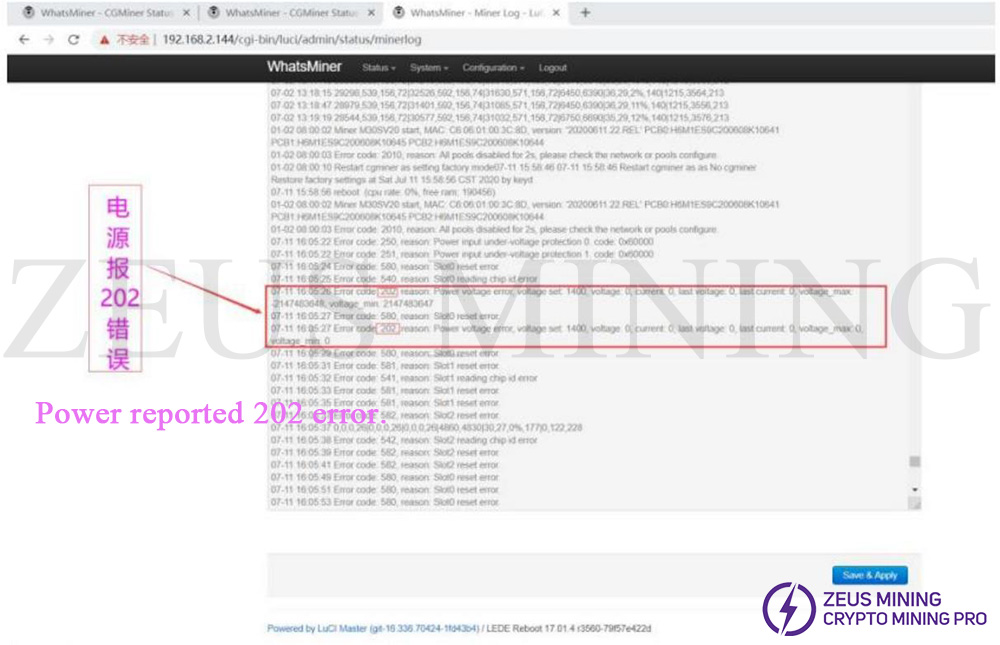
Exported the Miner log (as below) to further check the error reason. Per log, 202 error was caused by the power supply, replaced the power supply, and tested ok.
Case 8: M30+ Error code 257, 540, 541, 542, the solution same as last case.
IP screen:
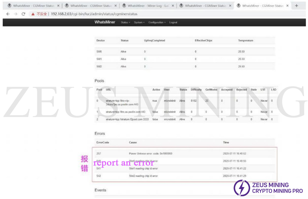
Further check the Miner Log status.
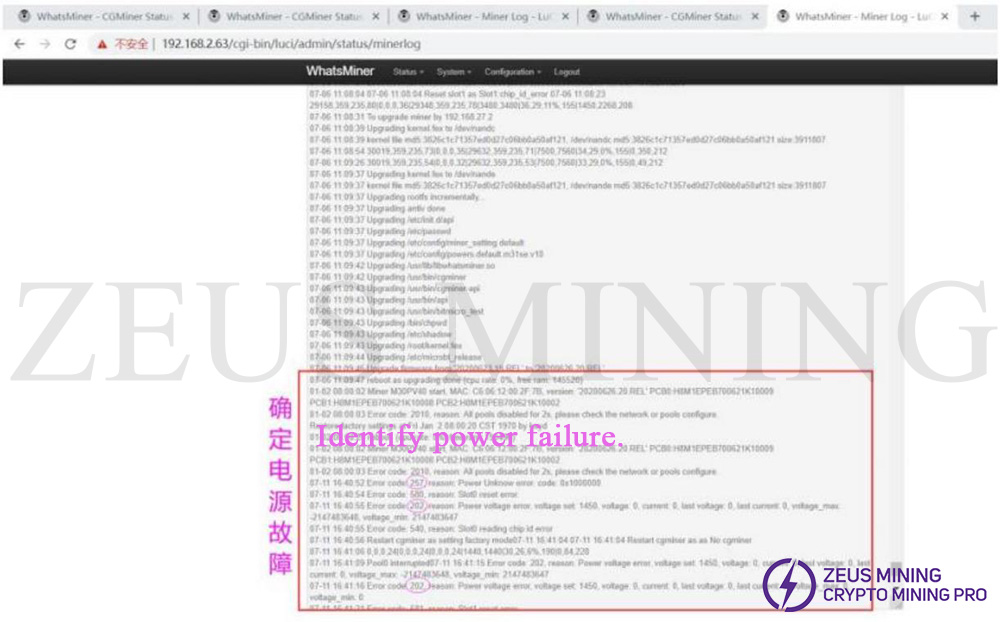
From the log, it can tell 202 & 257 errors caused by the power supply, replace the PSU and test OK.
Dear Customers,
Hello everyone, as China is about to usher in the Spring Festival, international logistics will be suspended. Zeus Mining is scheduled to stop shipping on February 11, 2026, and start the Spring Festival holiday from February 12 to February 23, 2026 (GMT+8). Pre-sales and after-sales service will reply to the information on February 24, 2026, and shipping will resume on February 24, 2026. Thank you for your support and trust in 2025. In 2026 and the future, we will bring better products and services to our friends.
Best wishes,
ZEUS MINING CO., LTD.